Transcription of LTC5596 - 100MHz to 40GHz Linear-in-dB RMS Power …
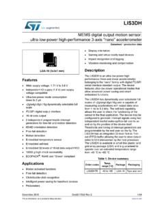
1 LTC559615596fFor more information applicaTion FeaTuresDescripTion100 MHz to 40 GHz Linear-in-dB RMS Power Detector with 35dB Dynamic RangeThe LT C 5596 is a high accuracy RMS Power detector that provides a very wide RF input bandwidth, from 100 MHz up to 40 GHz. This makes the device suitable for a wide range of RF and microwave applications, such as point-to-point microwave links, instrumentation and Power control DC output voltage of the detector is an accurate rep-resentation of the average signal Power applied to the RF input . The response is Linear-in-dB with 29mV/dB logarith-mic slope over a 35dB dynamic range with typically better than 1dB accuracy. The detector is particularly suited for measurement of waveforms with crest factor (CF) as high as 12dB, and waveforms that exhibit a significant variation of the crest factor during the achieve higher accuracy and lower output ripple, the averaging bandwidth can be externally adjusted by a ca-pacitor connected between the FLTR and OUT enable interface switches the device between active measurement mode and a low Power shutdown to 40 GHz RMS Power DetectorOutput Voltage vs FrequencyapplicaTionsL, LT, LTC, LTM, Linear Technology and the Linear logo are registered trademarks of Linear Technology Corporation.
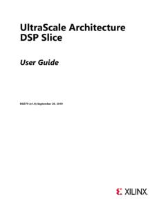
2 All other trademarks are the property of their respective owners. Protected by patents, including 9330283 ultra wide Matched input Frequency Range: 100 MHz to 40 GHzn 35dB Linear Dynamic Range (< 1dB Error)n 29mV/dB Logarithmic Slopen 1dB Flat Response from 200 MHz to 30 GHzn Accurate RMS Power Measurement of High Crest Factors (Up to 12dB) Modulated Waveformsn Low Power Shutdown Moden Low Supply Current: 30mA at (Typical)n Small 2mm 2mm Plastic DFN8 Packagen I-Grade: 40 C to 105 C Rated H-Grade: 40 C to 125 C Rated with Guaranteed Log-Slope and Log-Interceptn ESD Rating: 3500V HBM, 1500V CDMn Point-to-Point Microwave Linksn Instrumentation and Measurement Equipmentn Military Radiosn LTE, WiFi, WiMax Wireless Networksn RMS Power Measurement n Receive and Transmit Gain Controln RF PA Transmit Power TA01aLTC5596100nF1 ENABLEADCCFLTRRFIN5596 FREQUENCY (GHz)OUTPUT VOLTAGE (V)0dBm 5dBm 10dBm 15dBm 20dBm 25dBm 30dBm 35dBmLTC559625596fFor more information conFiguraTionabsoluTe MaxiMuM raTings(Note 1)TOP VIEWDC PACKAGE8-LEAD (2mm 2mm) PLASTIC DFN41236578 ENGNDRFINGNDVCCOUTFLTRGND9 TJMAX = 150 C, JC = 25 C/W EXPOSED PAD (PIN 9) IS GND, MUST BE SOLDERED TO PCBorDer inForMaTionelecTrical characTerisTicsPARAMETERCONDITIONSI-GRAD E (NOTE 3)H-GRADE (NOTE 4)UNITSMINTYPMAXMINTYPMAXRF InputInput Frequency to to 40 GHzInput Impedance52||5052||50 ||fFDetector Response (RFIN to OUT)
3 RF input Power Range, TC = 25 C 1dB LOG-Linearity Error (Note 5, 6)fRF = 50 MHz to to = 100 MHz to to = 500 MHz to to = to to = to to = to to = 10 GHz to to = 12 GHz to to = 15 GHz to to = 18 GHz to to = 24 GHz to to FREE FINISHTAPE AND REELPART MARKING*PACKAGE DESCRIPTIONTEMPERATURE RANGELTC5596 IDC#PBFLTC5596 IDC#TRPBFLGNN8-Lead 2mm 2mm Plastic DFN 40 C to 105 CLTC5596 HDC#PBFLTC5596 HDC#TRPBFLGNN8-Lead 2mm 2mm Plastic DFN 40 C to 125 CConsult LTC Marketing for parts specified with wider operating temperature ranges . *The temperature grade is identified by a label on the shipping more information on lead free part marking, go to: For more information on tape and reel specifications, go to: Some packages are available in 500 unit reels through designated sales channels with #TRMPBF #orderinfo The l denotes the specifications which apply over the full operating temperature range, otherwise specifications are at TC = 25 C.
4 VCC = , EN = CW, 50 source at RFIN, fRF = 2140 MHz, test circuit is shown in Figure 1. (Note 2).Supply Voltage (VCC) .. input Signal Power - Average ..15dBmRFIN input Signal Power - Peak (Note 2) ..20dBmDC Voltage at RFIN .. to 1 VDC Voltage at FLTR .. to Voltage at EN .. to ..150 CCase Operating Temperature Range (TC): I-Grade (Note 3) .. 40 C to 105 C H-Grade (Note 4) .. 40 C to 125 CStorage Temperature Range .. 65 C to 150 CLTC559635596fFor more information characTerisTics The l denotes the specifications which apply over the full operating temperature range, otherwise specifications are at TC = 25 C. VCC = , EN = CW, 50 source at RFIN, fRF = 2140 MHz, test circuit is shown in Figure 1.
5 (Note 2).PARAMETERCONDITIONSI-GRADE (NOTE 3)H-GRADE (NOTE 4)UNITSMINTYPMAXMINTYPMAXfRF = 26 GHz to to = 28 GHz to to = 30 GHz to to = 35 GHz to to = 38 GHz to to = 40 GHz to to = to to input Power Range Over Operating Temperature Range 1dB LOG-Linearity Error (Note 5, 6)fRF = 50 MHzl to to = 100 MHzl to to = 500 MHzl to to = to to = to to = to to = 10 GHzl to to = 12 GHzl to to = 15 GHzl to to = 18 GHzl to to = 24 GHzl to to = 26 GHzl to to = 28 GHzl to to = 30 GHzl to to LOG-Linearity ErrorfRF = 35 GHzl to to LOG-Linearity ErrorfRF = 38 GHzl to to LOG-Linearity ErrorfRF = 40 GHzl to to LOG-Linearity ErrorfRF = to to Dynamic Range, TC = 25 C (Note 6)fRF = = = = = = = = = = = = = = more information (NOTE 3)H-GRADE (NOTE 4)UNITSMINTYPMAXMINTYPMAXfRF = = = = Dynamic Range Over Operating Temperature Range (Note 6)
6 FRF = = = = = = = = = = = = = = dB LOG-Linearity ErrorfRF = dB LOG-Linearity ErrorfRF = dB LOG-Linearity ErrorfRF = 40 GHzl34, dB LOG-Linearity ErrorfRF = Slope, TC = 25 C (Note 7)fRF = = = = = = = = = = = = = = = = = = characTerisTics The l denotes the specifications which apply over the full operating temperature range, otherwise specifications are at TC = 25 C. VCC = , EN = CW, 50 source at RFIN, fRF = 2140 MHz, test circuit is shown in Figure 1. (Note 2).LTC559655596fFor more information (NOTE 3)H-GRADE (NOTE 4)UNITSMINTYPMAXMINTYPMAXL ogarithmic Slope Over Operating Temperature Range (Note 7)fRF = to to = to to = to to = to to = to to = to to = to to = to to = to to = to to = to to = to to = to to = to to = to to = to to = to to = to to Intercept, TC = 25 C (Note 8) fRF = 50 MHz = 100 MHz = 500 MHz = = = = 10 GHz = 12 GHz = 15 GHz = 18 GHz = 24 GHz = 26 GHz = 28 GHz = 30 GHz = 35 GHz = 38 GHz = 40 GHz = Intercept Over Operating Temperature Range (Note 8)
7 FRF = 50 MHzl to to = 100 MHzl to to = 500 MHzl to to = to to characTerisTics The l denotes the specifications which apply over the full operating temperature range, otherwise specifications are at TC = 25 C. VCC = , EN = CW, 50 source at RFIN, fRF = 2140 MHz, Test circuit is shown in Figure 1. (Note 2).LTC559665596fFor more information (NOTE 3)H-GRADE (NOTE 4)UNITSMINTYPMAXMINTYPMAXfRF = to to = to to = 10 GHzl to to = 12 GHzl to to = 15 GHzl to to = 18 GHzl to to = 24 GHzl to to = 26 GHzl to to = 28 GHzl to to = 30 GHzl to to = 35 GHzl to to = 38 GHzl to to = 40 GHzl to to = to to Dynamic Range for VariousCDMA 9Ch fwd to to Formats (Note 9)CDMA 32Ch fwd to to 64Ch fwd to to 3 Carriers to to 4 Carriers to to 1Ch Up to to 1Ch Down to to 2 Carriers to to 3 Carriers to to 4 Carriers to to 5 MHz BW to to 10 MHz BW to to 15 MHz BW to to Delay (Note 10)
8 Pin from 55dBm to sOUT InterfaceOutput DC VoltageNo RF Signal Present EN = = 10dBm EN = Voltage Droop25mA Sourcing 35620 35620mV25mA Sinking3030mVIntegrated Output Noise1kHz to PIN = 0dBm2222 VRMSRise Time (Note 11)50 Load at sFall Time (Note 12)50 Load at selecTrical characTerisTics The l denotes the specifications which apply over the full operating temperature range, otherwise specifications are at TC = 25 C. VCC = , EN = CW, 50 source at RFIN, fRF = 2140 MHz, input Power PIN = 0dBm, test circuit is shown in Figure 1. (Note 2).LTC559675596fFor more information (NOTE 3)H-GRADE (NOTE 4)UNITSMINTYPMAXMINTYPMAXE nable (EN) Low = Off, High = OnEN input High Voltage (On) input Low Voltage (Off) Pin input Current5050050500nATurn ON Time (Note 13)50 Load at OUT88 sTurn OFF Time (Note 14)50 Load at OUT 1M ||11pF Load at OUT45 10045 100ns sPower SupplySupply Supply CurrentEN = Supply CurrentEN = 0V5050050500nAelecTrical characTerisTics The l denotes the specifications which apply over the full operating temperature range, otherwise specifications are at TC = 25 C.
9 VCC = , EN = CW, 50 source at RFIN, fRF = 2140 MHz, Test circuit is shown in Figure 1. (Note 2).50 MHz to 38 GHz, and is added for 40 GHz and to center the errors over the full temperature range. See also the Application Section for an explanation of measurement error 6: Range for which the LOG-Linearity Error is within 7: Slope of the best fit straight line obtained by linear 8: Extrapolated input Power level (straight line obtained by linear regression) where the voltage at OUT equals 9: Power range for which LOG-Linearity Error is within 1dB, relative to best fit straight line for CW data (see Note 5).Note 10: Delay from 50% change in RFIN to 50% change in output 11: Time required to change voltage at OUT pin from 10% to 90% of final value. input Power stepped from 55dBm to 12: Time required to change voltage at OUT pin from 90% to 10% of initial value.
10 input Power stepped from 0dBm to 13: Time required to change voltage at OUT pin to 90% of final value. input Power 14: Time required to change voltage at OUT pin to 10% of initial value. input Power 0dBm. For higher load impedance the turn-off time will be (much) larger as the OUT interface is high impedance in shutdown 1: Stresses beyond those listed under Absolute Maximum Ratings may cause permanent damage to the device. Exposure to any Absolute Maximum Rating condition for extended periods may affect device reliability and lifetime. The voltage on all pins should not exceed , VCC + or be less than , otherwise damage to the ESD diodes may 2: Not production tested. Guaranteed by design and correlation to production tested 3: The LTC5596 IDD is guaranteed functional over the case temperature range 40 C to 105 C. All limits at 40 C and 105 C are guaranteed by design and production sample testing.