Transcription of LTL2V3EW3K Product Data Sheet Through Hole Lamp
1 Through Hole Lamp Product Data Sheet LTL2V3EW3K . Spec No.: DS20-2014-0071. Effective Date: 09/23/2014. Revision: - LITE-ON DCC. RELEASE. BNS-OD-FC001/A4. LITE-ON Technology Corp. / Optoelectronics ,Chien 1 Road, Chung Ho, New Taipei City 23585, Taiwan, Tel: 886-2-2222-6181 Fax: 886-2-2221-1948 / 886-2-2221-0660. Through Hole Lamp LTL2V3EW3K . Through Hole Lamp LTL2V3EW3K . Rev Description By Date Above data for PD and Customer tracking only - Upload OPNC and NPPR received. Craig 09/10/2014. Part No.
2 : LTL2V3EW3K . 1/9 BNS-OD-FC002/A4. Through Hole Lamp LTL2V3EW3K . 1. Description 5mm round lamp is a popular design with a smooth uniform view angle radiation pattern suitable in Full color signboard, Billboard sign, Message sign and bus sign. High luminous intensity output has a higher emitting efficiency to save power energy. Advanced epoxy technology has a good moisture resistance and UV protection to be used in package, and it can reduce the effect of long term exposure in outdoor environment.
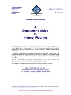
3 1. 1. Features Applications High Luminous intensity output. Video message sign Low power consumption & High efficiency. Traffic sign Superior resistance to moisture Message sign Good UV inhibitor Bus sign Lead free & RoHS Compliant Popular T-1 3/4diameter, Red AlInGaP 625nm Lamp, Water clear package. Minimum viewing angle 30 . 2. Outline Dimensions Notes : 1. All dimensions are in millimeters (inches). 2. Tolerance is (.010") unless otherwise noted. 3. Protruded resin under flange is (.04") max. 4.
4 Lead spacing is measured where the leads emerge from the package. 5. Specifications are subject to change without notice. Part No. : LTL2V3EW3K . 2/9 BNS-OD-FC002/A4. Through Hole Lamp LTL2V3EW3K . 3. Absolute Maximum Ratings at TA=25 . Parameter Maximum Rating Unit Power Dissipation 125 mW. Peak Forward Current (Duty Cycle 1/10, Pulse Width 10ms) 100 mA. DC Forward Current 50 mA. Derating Linear From 4 mA/ . Reverse Voltage 5 V. Operating Temperature Range -30 C to + 85 C. Storage Temperature Range -40 C to + 100 C.
5 Lead Soldering Temperature [ (.079") From Body] 260 C for 5 Seconds Max. 4. Electrical / Optical Characteristics at TA=25 . Parameter Symbol Min. Typ. Max. Unit Test Condition IF = 20mA. Luminous Intensity IV 5500 12000 mcd Note 1,5. Viewing Angle 2 1/2 30 deg Note 2,7 ( ). Measurement Peak Emission Wavelength P 631 nm @Peak ( ). Dominant Wavelength d 619 630 nm Note 4. Spectral Line Half-Width 17 nm Forward Voltage VF V IF = 20mA. Reverse Current IR 100 A VR = 5V. NOTE: 1. Luminous intensity is measured with a light sensor and filter combination that approximates the CIE eye-response curve.
6 2. 1/2 is the off-axis angle at which the luminous intensity is half the axial luminous intensity. 3. Iv classification code is marked on each packing bag. 4. The dominant wavelength, d is derived from the CIE chromaticity diagram and represents the single wavelength which defines the color of the device. 5. Iv guarantee must be included with 15% testing tolerance. 6. Reverse voltage (VR) condition is applied for IR test only. The device is not designed for reverse operation. 7. View angle measurement is 2 degree tolerance.
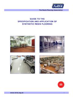
7 Part No. : LTL2V3EW3K . 3/9 BNS-OD-FC002/A4. Through Hole Lamp LTL2V3EW3K . 5. Typical Electrical / Optical Characteristics Curves (25 Ambient Temperature Unless Otherwise Noted). Part No. : LTL2V3EW3K . 4/9 BNS-OD-FC002/A4. Through Hole Lamp LTL2V3EW3K . 6 Packing Spec. 1000, 500 or 250 pcs per packing bag 8 Packing bags per inner carton Total 8,000 pcs per inner carton 8 Inner cartons per outer carton Total 64,000 pcs per outer carton In every shipping lot, only the last pack will be non-full packing Part No.
8 : LTL2V3EW3K . 5/9 BNS-OD-FC002/A4. Through Hole Lamp LTL2V3EW3K . 7 Bin Table Specification Luminous Intensity Iv (mcd) Bin Code Min. Max. W 5500 7200. X 7200 9300. Y 9300 12000. Note: Tolerance of each bin limit is 15%. Forward Voltage Vf Unit : V Bin Code Min Max 1 2 3 4 5 6 Note: Tolerance of each bin limit is Part No. : LTL2V3EW3K . 6/9 BNS-OD-FC002/A4. Through Hole Lamp LTL2V3EW3K . 8. CAUTIONS. Application This LED lamp is good for application of indoor and outdoor sign, also ordinary electronic equipment.
9 Storage The storage ambient for the LEDs should not exceed 30 C temperature or 70% relative humidity. It is recommended that LEDs out of their original packaging are used within three months. For extended storage out of their original packaging, it is recommended that the LEDs be stored in a sealed container with appropriate desiccant or in desiccators with nitrogen ambient. Cleaning Use alcohol-based cleaning solvents such as isopropyl alcohol to clean the LEDs if necessary. Lead Forming & Assembly During lead forming, the leads should be bent at a point at least 3mm from the base of LED lens.
10 Do not use the base of the lead frame as a fulcrum during forming. Lead forming must be done before soldering, at normal temperature. During assembly on PCB, use minimum clinch force possible to avoid excessive mechanical stress. Soldering When soldering, leave a minimum of 3mm clearance from the base of the lens to the soldering point. Dipping the lens into the solder must be avoided. Do not apply any external stress to the lead frame during soldering while the LED is at high temperature. Recommended soldering conditions: Soldering iron Wave soldering Temperature 350 C Max.