Transcription of M2000 Engine Controller - SELCO
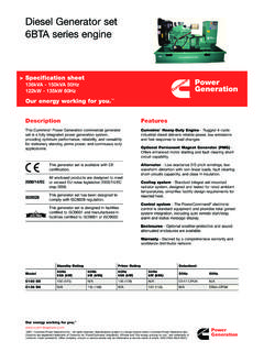
1 M2000 Engine ControllerIntegrated control and protection of diesel and gas engines for all purposes Type approved by major marine classification societies Compact unit for switchboard front panel mounting with standard instrument dimensions of 144 x 144 and a depth of only 35 mm Contains 9 shutdown channels and/ or 7 alarm channels selectable Two powerful LEDs for each of the 10 indicating channels with windows for identification CE mark according to EN 50081 and 50082 Internal tacho relay and program mable check of external circuit Quick installation by means of clamping fittings and plug-in terminal blocks for easy service Microcomputer based circuit designed for high noise immunity and high supply voltage variations Contains automatic test function and control of intermittent prelubrication of Engine The blank legend card can be typed or printed and inserted between the front plates as illustrated Auxiliary options: M0100 Battery Back-up.
2 M0500 Tacho-voltage Detector. M0800 IP54 Cover. When stopping the Engine by deactivating terminal 2, a gene rator circuit breaker trip delay is available ( min.). Finally a shutdown delay is available for cooling purposes (0-2-4-10 min.). The stated sequence times are standard, but can be altered to suit using SELCO PC programmer N0500. Besides the above main functions, the Controller contains many other 1. Quick and easy replacement of text SELCO Engine Controller M2000 has been designed to handle the complete control of a diesel generator. It controls start and stop of the Engine , monitors and protects the Engine during start and operation, and simultaneously indicates on the front all necessary information about the conditions of the generator is obtained by activating input terminal 2 and after start delay ( secs) the start will be initiated.
3 It is possible to select up to 4 start attempts, with both crank and rest periods adjustable (5-7-10-15 secs).When the Engine fires, termi nal 9 will be activated from an external tacho relay (crank disconnect) or the internal tacho unit detects in excess of 33% of the nominal frequency, and the cranking will be disconnected. CONTROLLERPOWERON1098765432110987654321 TESTRESETSTARTSTOPHIGH WATER OIL FAILIN OPERATIONE specially suited for auxiliary generator sets138mm138mm144mm144mmInputs Terminal 1: PUSH START / INSTANT RESTART. (Is active only in manual mode). NO contact to minus. Cranking is obtained as long as 1 is activated, and crank is disconnected by receiving crank disconnect signal. Several start attempts and start failure are not in function.
4 With S10 OFF, an sec. signal on terminal 1 gives start, and start failure and more start attempts are active. Is 1 connected to minus via kW, start in the stop periode is obtained. The fuel valve will open and the stop coil released but cranking is only possible after the stop time has passed. Terminal 2: START / STOP.(Is active only in automatic mode). NO contact to minus. By activation the Engine is started, and by deactivation the Engine is stopped. Terminal 3: external 3-position switch is connected here. MANUAL (MAN.) is obtained by con-necting terminal 3 to plus, and in that position start and stop can be performed via the push button on the front, and via the terminals 1 and (AUT.) with terminal 3 open, automatic start and stop is obtained by activating or deactivating terminal 2.
5 OFF is obtained by connecting terminal 3 to minus, and in this position the Engine is stopped and blocked for : Is OFF considered as safety switch-off, then 18 (CRANK) must also be disconnected. Terminal 4: STOP + ALARM CHANNEL contact to minus. The input is enabled 8 sec. after crank disconnect. This channel can be used for any Engine protection or alarm function. Gives shut-down, alarm, and fast flashing on LED 7. Contains possibility of circuit check or alarm by connecting input 16 to minus and mounting kW across the contact. If this connection is broken or opened an alarm will be indicated by slow flashing LEDs. Terminal 5: STOP + ALARM CHANNEL 8. NO contact to minus. Shut-down is enabled 8 sec.
6 After crank disconnect. Alarm is in operation with Engine not running. This channel can be used for any motor protection or alarm function. Gives shut-down, alarm, and fast flashing on LED 8. Contains possibility of circuit check or alarm by connecting input 16 to minus and mounting kW across the contact. If this connection is broken or opened an alarm will be indicated by slowflashing LEDs. With input to plus, indication without any logical function is obtained. Terminal 6: STOP + ALARM CHANNEL contact to minus. Shut-down is enabled 8 sec. after crank disconnect. Alarm is in operation with Engine not running. This channel can be used for any motor protection or alarm function.
7 Gives shut-down, alarm, and fast flashing on LED 9. Contains possibility of circuit check or alarm by connecting input 16 to minus and mounting kW across the contact. If this connection is broken or opened an alarm will be indicated by slow flashing LEDs. With input to plus, indication without any logical function is obtained. Terminal 7: STOP + ALARM / EMERGENCY STOP CHANNEL 10. NO contact to minus. Shut-down is enabled 8 sec. after crank disconnect. Alarm is in operation with Engine not running. This channel can be used for any motor protection or alarm function. Gives shut-down, alarm, and fast flashing on LED 10. Contains possibility of circuit check or alarm by connecting input 16 to minus and mounting kW across the contact.
8 If this connection is broken or opened an alarm will be indicated by slow flashing LEDs. With input 7 to plus, emergency stop with shut-down and blocking is obtained. This functions is also active with Engine not running. Terminal 8: TACHO generator frequency is measured via the attached tacho detector M0500. If contact S15 is OFF, 33% of the nominal frequency (system frequency 50 or 60 Hz chosen on terminal 9) is crank disconnect, and 115% is over-speed. The first 8 sec. after start the limit is 120%. Terminal 9: CRANK DISCONNECT/ SYSTEM FREQUENCY. NO contact to minus. With programming contact S15 ON, an external contact signal for disconnecting cranking can be connected, for instance a tacho relay indicating that the Engine is running.
9 If the programming contact S15 is OFF, the internal tacho function is active with tacho detector M0500, and the system frequency is programmed on this terminal as follows : 9 to minus = 60 Hz, 9 open = 50 Hz. Terminal 10: contact to minus. An external tacho relay set for the Engine overspeed is connected and gives shut-down, and flashing on LED 3 labelled OVERSPEED . This input terminal is active independent of S15 position. In connection with tacho detector M0500 overspeed level 100% for test is obtained with terminal 10 to plus. Terminal 11: REMOTE ACCEPT / RESET / LAMP TEST. Two functions are obtained on this input in connection with failures on the Engine . The input connected to minus via a kW will disconnect the siren.
10 The input connected to plus directly will reset the alarm and release the blocking allowing the Engine to start again, provided the siren is disconnected. The input connected to minus gives disconntection of siren and alarm reset. Terminal 12: PUSH STOP / DELOADED TRIPTwo functions are obtainable. NO contact to minus. The Engine is stopped as long as 12 is activated. Is active only in manual mode. With S10 disconnected an sec. impulse on terminal 12 will give continuous stop. Engine stop will be delayed if circuit breaker trip delay and cool down time functions are selected, and all automatic functions are obtainable. Is 12 connected to minus via kW deloaded trip is obtained to be used on parallel running generator.