Transcription of MACHINING OPERATIONS AND MACHINE TOOLS
1 2002 John Wiley & Sons, Inc. M. P. Groover, Fundamentals of Modern manufacturing 2/e MACHINING OPERATIONS ANDMACHINE TOOLS Turning and Related OPERATIONS Drilling and Related OPERATIONS Milling MACHINING Centers and Turning Centers Other MACHINING OPERATIONS High Speed MACHINING 2002 John Wiley & Sons, Inc. M. P. Groover, Fundamentals of Modern manufacturing 2/e MachiningA material removal process in which a sharp cutting toolis used to mechanically cut away material so that thedesired part geometry remains Most common application: to shape metal parts MACHINING is the most versatile and accurate of allmanufacturing processes in its capability to producea diversity of part geometries and geometric features Casting can also produce a variety of shapes, butit lacks the precision and accuracy of MACHINING 2002 John Wiley & Sons, Inc.
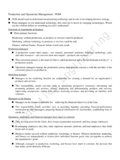
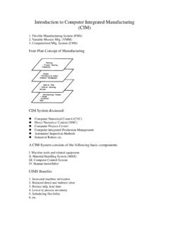
2 M. P. Groover, Fundamentals of Modern manufacturing 2/e Classification of Machined or disk-like (also calledprismatic)-block-like orplate-likeFigure parts are classified as: (a) rotational, or (b)nonrotational, shown here by block and flat parts 2002 John Wiley & Sons, Inc. M. P. Groover, Fundamentals of Modern manufacturing 2/e MACHINING OPERATIONS and Part GeometryEach MACHINING operation produces a characteristic partgeometry due to two motions between the tool and theworkpart Generating part geometry is determined bythe feed trajectory of the cutting of the cutting tool Forming part geometry is created by theshape of the cutting tool 2002 John Wiley & Sons, Inc. M. P. Groover, Fundamentals of Modern manufacturing 2/e Figure shape: (a) straight turning, (b) taperturning, (c) contour turning, (d) plain milling, (e) profile milling 2002 John Wiley & Sons, Inc.
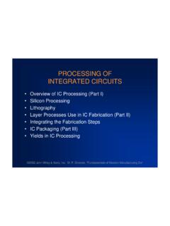
3 M. P. Groover, Fundamentals of Modern manufacturing 2/e Figure to create shape: (a) form turning, (b) drilling,and (c) broaching 2002 John Wiley & Sons, Inc. M. P. Groover, Fundamentals of Modern manufacturing 2/e Figure of forming and generating to createshape: (a) thread cutting on a lathe, and (b) slot milling 2002 John Wiley & Sons, Inc. M. P. Groover, Fundamentals of Modern manufacturing 2/e TurningA single point cutting tool removes material from arotating workpiece to generate a cylindrical shape Performed on a MACHINE tool called alathe Variations of turning that are performed on a lathe: Facing Contour turning Chamfering Cutoff Threading 2002 John Wiley & Sons, Inc. M. P.
4 Groover, Fundamentals of Modern manufacturing 2/e Figure operation 2002 John Wiley & Sons, Inc. M. P. Groover, Fundamentals of Modern manufacturing 2/e Figure (a) facingFacingTool is fedradially inward 2002 John Wiley & Sons, Inc. M. P. Groover, Fundamentals of Modern manufacturing 2/e Contour TurningInstead of feeding the tool parallel to the axis of rotation,tool follows a contour that is other than straight, thuscreating a contoured formFigure (c) contour turning 2002 John Wiley & Sons, Inc. M. P. Groover, Fundamentals of Modern manufacturing 2/e ChamferingCutting edge cuts an angle on the corner of the cylinder,forming a "chamfer"Figure (e) chamfering 2002 John Wiley & Sons, Inc.
5 M. P. Groover, Fundamentals of Modern manufacturing 2/e CutoffTool is fed radially into rotating work at some location tocut off end of partFigure (f) cutoff 2002 John Wiley & Sons, Inc. M. P. Groover, Fundamentals of Modern manufacturing 2/e ThreadingPointed form tool is fed linearly across surface ofrotating workpart parallel to axis of rotation at a largefeed rate, thus creating threadsFigure (g) threading 2002 John Wiley & Sons, Inc. M. P. Groover, Fundamentals of Modern manufacturing 2/e Figure ofan enginelathe,showing itsprincipalcomponents 2002 John Wiley & Sons, Inc. M. P. Groover, Fundamentals of Modern manufacturing 2/e Methods of Holding the Work in a Lathe Holding the work between centers Chuck Collet Face plate 2002 John Wiley & Sons, Inc.
6 M. P. Groover, Fundamentals of Modern manufacturing 2/e Holding the Work Between CentersFigure (a) mounting the work between centers using a "dog 2002 John Wiley & Sons, Inc. M. P. Groover, Fundamentals of Modern manufacturing 2/e ChuckFigure (b) three-jaw chuck 2002 John Wiley & Sons, Inc. M. P. Groover, Fundamentals of Modern manufacturing 2/e ColletFigure (c) collet 2002 John Wiley & Sons, Inc. M. P. Groover, Fundamentals of Modern manufacturing 2/e Face PlateFigure (d) face plate for non-cylindrical workparts 2002 John Wiley & Sons, Inc. M. P. Groover, Fundamentals of Modern manufacturing 2/e Turret LatheTailstock replaced by turret that holds up to six TOOLS TOOLS rapidly brought into action by indexing theturret Tool post replaced by four-sided turret to index fourtools Applications: high production work that requires asequence of cuts on the part 2002 John Wiley & Sons, Inc.
7 M. P. Groover, Fundamentals of Modern manufacturing 2/e Chucking MACHINE Uses chuck in its spindle to hold workpart No tailstock, so parts cannot be mounted betweencenters Cutting tool actions controlled automatically Operator s job: to load and unload parts Applications: short, light-weight parts 2002 John Wiley & Sons, Inc. M. P. Groover, Fundamentals of Modern manufacturing 2/e Bar MACHINE Similar to chucking MACHINE except collet replaceschuck, permitting long bar stock to be fed throughheadstock At the end of the MACHINING cycle, a cutoff operationseparates the new part Highly automated (the termautomatic bar machineisoften used) Applications: high production of rotational parts 2002 John Wiley & Sons, Inc.
8 M. P. Groover, Fundamentals of Modern manufacturing 2/e Automatic Screw MACHINE Same as automatic bar MACHINE but smaller Applications: high production of screws and similarsmall hardware items; hence, its name 2002 John Wiley & Sons, Inc. M. P. Groover, Fundamentals of Modern manufacturing 2/e Multiple Spindle Bar Machines More than one spindle, so multiple parts machinedsimultaneously by multiple TOOLS Example: six spindle automatic bar MACHINE workson six parts at a time After each MACHINING cycle, spindles (includingcollets and workbars) are indexed (rotated) to nextposition 2002 John Wiley & Sons, Inc. M. P. Groover, Fundamentals of Modern manufacturing 2/e Figure (a) Part produced on a six-spindle automatic barmachine; and (b) sequence of OPERATIONS to produce the part: (1)feed stock to stop, (2) turn main diameter, (3) form seconddiameter and spotface, (4) drill, (5) chamfer, and (6) cutoff 2002 John Wiley & Sons, Inc.
9 M. P. Groover, Fundamentals of Modern manufacturing 2/e Boring Difference between boring and turning: Boringis performed on the inside diameter of anexisting hole Turningis performed on the outside diameter ofan existing cylinder In effect, boring is an internal turning operation Boring machines Horizontal or vertical-refers to the orientation ofthe axis of rotation of MACHINE spindle 2002 John Wiley & Sons, Inc. M. P. Groover, Fundamentals of Modern manufacturing 2/e Figure vertical boring mill for large, heavy workparts 2002 John Wiley & Sons, Inc. M. P. Groover, Fundamentals of Modern manufacturing 2/e Drilling Creates a round hole ina workpart Contrasts with boringwhich can only enlargean existing hole Cutting tool called adrillordrill bit Customarily performedon adrill pressFigure (b) drilling 2002 John Wiley & Sons, Inc.
10 M. P. Groover, Fundamentals of Modern manufacturing 2/e Through Holes vs. Blind HolesThrough-holes-drill exits the opposite side of workBlind-holes drill does not exit work on opposite sideFigure hole types: (a) through-hole, and (b) blind hole 2002 John Wiley & Sons, Inc. M. P. Groover, Fundamentals of Modern manufacturing 2/e ReamingUsed to slightlyenlarge a hole,provide bettertolerance ondiameter, andimprove surfacefinishFigure operationsrelated to drilling:(a) reaming 2002 John Wiley & Sons, Inc. M. P. Groover, Fundamentals of Modern manufacturing 2/e TappingUsed to provideinternal screwthreads on anexisting holeTool called atapFigure (b) tapping 2002 John Wiley & Sons, Inc.