Transcription of Manage & Understand Flange Face Damage
1 PUMPS & SYSTEMS July 2013 51 SEALING SENSEThe purpose of surface finish is to allow a gasket to conform to and seal the Flange face. Sealing Sense in the April 2008 Pumps & Systems discussed the importance of ensuring that the choice of gasket and surface finish work together to maintain the appropriate level of sealing stress on the gasket. This update identifies some of the typical Damage that occurs to a Flange face, what the effect is and discusses a way to identify the practical limits for sealinGA gasket s role is to seal the space between the mating sur- faces of a Flange connection. This is accomplished when the bolt load compresses the gasket to a level of tightness that allows it to fill the gap between the mating faces and fill the small imperfections in the sealing surfaces.
2 With proper Flange design and gasket installation, the stress on the gasket will be sufficient to create a bar-rier between the pressurized side of the gasket and hold it securely in place. All the paths of leakage are effectively blocked between the gasket and Flange . However, what if portions of the Flange face are damaged? Will the Flange leak if used or should the end user replace it? Let s look at Flange face Damage and its potential effect on gasket of DamaGeOver time and for any number of reasons, Damage can occur to Flange faces . Each damaged area will tend to create a potential leak path that the gasket must try to seal. Some common types of Flange surface Damage , their char-acteristics and possible causes are listed below: Scratches This type Damage is narrow and elongated with sharp, shallow bottoms.
3 However, depending on the force that created them, they can be deep. Frequently, this type Damage is created by a sharp object dragging across the Flange face. These objects may include the bristles of a wire brush or a tool, such as a chisel. Gouges These are wide and elongated with blunt, rounded bottoms and are created by a dull object drag-ging across the Flange face. Gouges can be caused by objects such as a screwdriver, Flange jack or chisel. Pits This Damage is usually small, somewhat rounded areas of concentrated material loss created by corrosion. Often, pits occur in clusters or groups. Dents This type Damage can be sharp or blunt non-elongated areas caused by some form of impact. Dents sometimes result from equipment collisions caused by positioning the mating flanges using cables and most common events that create surface finish Damage are indentations that occur from removing previ-ously used gasket material from the sealing surface.
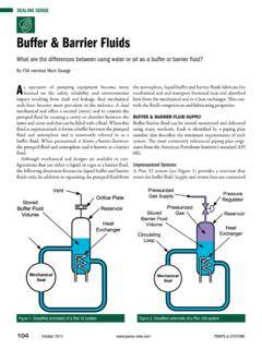
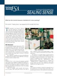
4 Tools, Manage & Understand Flange Face DamageWhat should I do about Flange face Damage : accept, repair or replace?By FSA member Randy WackerFigure 1. Flange surface Damage assessment. Reprinted from ASME PCC-1-2010, by permission of ASME. All rights SENSE52 July 2013 PUMPS & SYSTEMS such as chisels or screw drivers, should be avoided. A brass wire brush is preferred. Damage impactWhat the Damage types have in common is that they reduce the sealing tightness of the gasket against that particular (damaged) area of the Flange face. If these defects are small and few, the leak tightness of the bolted connection will not be significantly impacted. If a defect is large (especially across the radial direction of the Flange face) or several defects are grouped in a small area, the leak-age path can exceed the ability of the gasket to block it, and leakage can occur.
5 Whether the gasket can successfully seal these damaged areas depends on their size, depth, orientation and number. The question then becomes, how large is too large, or what is the limit on the number of small defects in a single area? Is the Flange fit to be returned to service? In 2010, the American Society of Mechanical Engineers (ASME) addressed this issue in its standard, Guidelines for Pressure Boundary Bolted Flange Joint Assembly, ASME PCC-1-2010. This standard provides guidance for several important Flange considerations. Appendix D of the stan-dard includes information that specifically addresses issues of Flange surface 1. Allowable defect depth versus width across a face. Reprinted from ASME PCC-1-2010, by permission of ASME.
6 All rights 140 on card or go to 133 on card or go to EXPERIENCEIN PRIVATE COMPANY TRANSACTIONSMEMBER FINRA, SIPCJ ordan, Knauff & Company is a knowledgeable and experienced provider of a comprehensive line of investment banking services to the pump, valve and filtration industries ( Flow Control ). Our lines of business include: selling companies, raising debt and equity capital, and assistance on acquisitions. To learn more about Jordan, Knauff & Company, contact any member of our Flow Control team. Access our Flow Control research at G. Cook Jordan, A. & SYSTEMS July 2013 53 Appendix D includes figures and tables that provide guidelines for setting allowable limits on Flange face defects. Specifically, it shows how to assess damaged portions of a Flange face by taking measurements of the defective areas (see Figure 1).
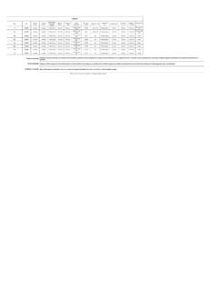
7 With these measurements, Table 1 can be accessed to determine the applicable limit for a particular type of Damage . Limits are established by determining the effective length (in the radial direction) and matching it to the depth of the same defect. The respective limit will depend on the type and category of gasket being used in the bolted Flange Gaskets Versus HarD GasketsThe ability of a gasket to seal a damaged area is similar to how a gasket seals against the surface finish of the Flange . It depends on how conformable the gasket is to the particular area of the Flange face surface. Soft gaskets are more capable of filling (and therefore sealing ) a defective area than hard gaskets. For this reason, the appendix divides its guidance into two categories of gaskets: soft gaskets and hard gaskets.
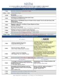
8 Each type has a different example, if a single gouge has a radial length of less than one-fourth of the gasket width, the permissible depth of the gouge is inch for a soft gasket. The identi-cal gouge on a hard gasket has a depth limit of only inch. See Table 1 for additional informa-tion. For any Damage type, end users must correctly categorize the type of gasket used and match it to Table 2. Flange seating face flatness tolerances. Reprinted from ASME PCC-1-2010, by permission of ASME. All rights TORNADO T2 Rotary Lobe Pump New Metal Lobe / Rubber Liner Design!NETZSCH Pumps North America, LLCTel: 610-363-8010email: Ground-breaking timing / drive design Full service-in-place Replaceable liner Lowest life cycle cost Cartridge seal technology Exceptional performance Superior durability Compact and robust Low pulsationcircle 124 on card or go to SENSE54 July 2013 PUMPS & SYSTEMSthe respective table provided in the standard and noted in this flatness limitsThe flatness of the Flange also affects a gasket s ability to seal.
9 A lack of Flange flatness can also be considered Damage . This can occur because of excessive loads on the Flange or as the result of errant machining of the Flange surface. Soft gaskets will also tend to conform to and seal areas of poor flatness better than a hard gasket. Again, the tolerance of a lack of flatness depends on whether the gasket is soft or example, a hard gasket can seal a lack of flatness in the radial direction that is less than inch. The limit for a soft gasket is inch. Guidelines are also included that set limits on a lack of flatness in the circumferential direction. See Table 2 for additional , replace or accept?The best policy is always to protect the Flange faces from any form of Damage . Plants should also establish a quality assurance program that verifies the flatness of new flanges and provides training for maintenance personnel on the acceptable limits as provided in the guidance of ASME PCC-1-2010, Appendix D.
10 This guidance provides the best available information for field personnel to determine whether to accept Flange face Damage , repair it or replace s Note: ASME reviews and rewrites its standards every three years. PCC-1-2010 has recently undergone its review and rewrite and is currently out for ballot. Once approved via the ballot process, PCC-1-2013 is expected to be published. The new document will offer further clarifi-cation regarding the details in this article. However, minor revisions to the information offered in this Sealing Sense are expected. P&Snext montH: What are the energy and water usage impacts of seal support systems?We invite your suggestions for article topics as well as questions on sealing issues so we can better respond to the needs of the industry.