Transcription of Managed PoE+ Gigabit Switch with SFP - Ubiquiti
1 Managed PoE+ Gigabit Switch with SFPM odel: US-16-150 WIntroductionThank you for purchasing the Ubiquiti Networks UniFi Switch . This Quick Start Guide is designed to guide you through the installation and also includes the warranty terms. Package ContentsUniFi Switch US-16-150 WPower CordRack-Mount Brackets (Qty. 2)Bracket Screws (Qty. 8) Managed PoE+ Gigabit Switch with SFPM odel: US-16-150 WMounting Screws (Qty. 4) Cage Nuts (Qty. 4)Rubber Feet (Qty. 4)Quick Start GuideIMPORTANT: We strongly recommend using UPS backup and power regulation to prevent equipment damage due to stability issues with local AC OF USE: All Ethernet cabling runs must use CAT5 (or above). It is the customer s responsibility to follow local country regulations, including operation within legal frequency channels, output power, indoor cabling requirements, and Dynamic Frequency Selection (DFS) Requirements Linux, Mac OS X, or Microsoft Windows 7/8/10 Java Runtime Environment ( or newer recommended) Web Browser: Google Chrome (Other browsers may have limited functionality.)
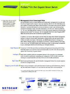
2 UniFi Controller software or above, available at: Requirements Phillips screwdriver (for rack-mounting) Standard-sized, 19" wide rack with a minimum of 1U height available (for rack-mounting) For indoor applications, use Category 5 (or above) UTP cabling approved for indoor use. For outdoor applications, shielded Category 5 (or above) cabling should be used for all wired Ethernet connections and should be grounded through the AC ground of the power recommend that you protect your networks from harmful outdoor environments and destructive ESD events with industrial-grade, shielded Ethernet cable from Ubiquiti Networks. For more details, visit : To reduce the risk of fire or electric shock, do not expose the Switch to rain or : Although the cabling can be located outdoors, the UniFi Switch itself should be housed inside a protective Topology Requirements A DHCP-enabled network for the UniFi Switch to obtain an IP address (connected devices will also obtain IP addresses after deployment) A UniFi Cloud Key or management station running the UniFi Controller software or above, located either on-site and connected to the same Layer 2 network, or off-site in a cloud or NOCUniFi Switch US-16-150 WUniFi Security Gateway Pro(DHCP Server)InternetUAP-AC-PROUAP-AC-LRUAP-IW LANWANUniFi Cloud Key(UniFi Controller)Remote Access toUniFi ControllerRemote Access toUniFi ControllerSample Network DiagramAll UniFi devices support off-site management controllers.
3 For setup details, refer to the User Guide on the website: OverviewFront PanelRJ45 1-16 SFP 1-2 Reset ButtonPortDescriptionRJ45 1-16RJ45 ports support Power over Ethernet (PoE) and 10/100/1000 Ethernet 1-2 Hot-swappable SFP ports support 1 Gbps ButtonThis button serves two functions for the UniFi Switch : Restart Press and release the Reset button quickly. Restore to Factory Default Settings Press and hold the Reset button for more than five Panel System LEDS ystemStateStatusWhiteFactory defaults, waiting for White/BlueDevice is busy; do not use or unplug it. This usually indicates that a process such as a firmware upgrade is taking integrated into a network and working BlueThis is used to locate a device. When you click Locate in the UniFi Controller software, the System LED will flash blue. The software will also display the location of the UniFi Switch on the Panel Port LEDsSFP Speed/Link/ActRJ45 Speed/Link/ActRJ45 PoELEDS tateStatusRJ45 1-16 PoEOffNo PoEAmberIEEE LinkAmberLink Established at 10/100 Mbps Flashing Indicates ActivityGreenLink Established at 1000 Mbps (1 Gbps)Flashing Indicates ActivitySFP 1-2 Speed/Link/ActivityOffNo LinkGreenLink Established at 1 GbpsFlashing Indicates ActivityBack PanelPowerConsoleVentilation FansPortDescriptionConsoleRJ45 serial console port for Command Line Interface (CLI) management.
4 Use an RJ45-to-DB9, serial console cable, also known as a rollover cable, to connect the Console port to your computer. Then configure the following settings as needed: Baud rate 115200 Data bits 8 Parity NONE Stop bits 1 Flow control NONEH ardware InstallationThe UniFi Switch can be placed on a horizontal surface, mounted in a rack, or mounted on a wall. WARNING: FAILURE TO PROVIDE PROPER VENTILATION MAY CAUSE FIRE HAZARD. KEEP AT LEAST 20 MM OF CLEARANCE NEXT TO THE VENTILATION HOLES FOR ADEQUATE in a Rack (Optional)1. Attach the Rack-Mount Brackets to the UniFi Switch using the eight Bracket Attach the UniFi Switch to the rack using the four Mounting Screws. (If the rack has square slots, use the Cage Nuts with the Mounting Screws.)Connecting Power1. Connect the Power Cord to the Power port of the UniFi Connect the other end of the Power Cord to a power Ethernet1.
5 Connect a UniFi Cloud Key, management computer, or LAN running the UniFi Controller to the UniFi Connect Ethernet cables from the gateway or router (DHCP server) and other devices to the UniFi SFP PortsTo use an SFP port:1. Remove the protective plug covering the SFP Plug a compatible fiber module into the SFP SM/SC 20KM DDMTx1550nm/Rx1310nm3. Connect the fiber optic cable to the fiber module. Then connect the other end of the cable to another fiber information about compatible fiber SFP modules, visit: InstallationDownload and install the latest version of the UniFi Controller software at and follow the on-screen : If you already have UniFi Controller or newer installed, skip to the section, Adopting the UniFi you have installed the software and run the UniFi Installation Wizard, a login screen will appear for the UniFi Controller management interface.
6 Enter the admin name and password that you created and click Log In. You can manage your network and view network statistics using the UniFi Controller management interface. To adopt the UniFi Switch , proceed to the Adopting the UniFi Switch information on configuring and using the UniFi Controller software, refer to the User Guide on the website: the UniFi Switch1. From the UniFi Controller dashboard, click Devices in the left menu On the Devices screen, locate the UniFi Switch in the list of devices under the Model column. To adopt the UniFi Switch , click The System LED on the UniFi Switch will turn blue to confirm that it has been successfully adopted.*640-00172-04*640-00172-04 Configuring PoE SettingsThe RJ45 ports are auto-sensing by default, so devices can be plugged in and automatically receive Power over Ethernet. To disable or enable PoE, follow these instructions:1.
7 On the Devices screen, locate the UniFi Switch in the list of devices under the Model column. Click its Name/MAC Address to access its Click the Ports Click Actions for the port you want to Select the appropriate PoE setting: Off or PoE+. Then click more information, refer to the User Guide on the website: Switch US-16-150 WDimensions443 x 43 x 221 mm ( x x ")WeightWith Mount Brackets kg ( lb) kg ( lb)Total Non-Blocking Line Rate18 GbpsMax. Power Consumption150 WPower Method100-240 VAC/50-60 Hz, Universal InputPower SupplyAC/DC, Internal, 150W DCRack-MountYes, 1U HighLEDs Per PortRJ45 Data PortsSFP Data PortsPoE, Speed/Link/ActivitySpeed/Link/ActivityIn terfacesNetworking Interfaces Management Interface(16) 10/100/1000 Mbps RJ45 Ports (2) 1 Gbps SFP PortsEthernet In-Band, Serial Console Out-of-Band (Reserved for Future Use)PoE Output (RJ45 Ports)PoE+ IEEE (pins 1, 2+; 3, 6-)PoE Voltage Range Mode50-57 VMax.
8 PoE+ Wattage per Temperature-5 to 40 C (23 to 104 F)Operating Humidity5 to 95% NoncondensingShock and StandardCertificationsCE, FCC, ICSafety Notices1. Read, follow, and keep these Heed all Only use attachments/accessories specified by the : Failure to provide proper ventilation may cause fire hazard. Keep at least 20 mm of clearance next to the ventilation holes for adequate : To reduce the risk of fire or electric shock, do not expose this product to rain or moisture. WARNING: Do not use this product in location that can be submerged by water. WARNING: Avoid using this product during an electrical storm. There may be a remote risk of electric shock from lightning. Electrical Safety Information1. Compliance is required with respect to voltage, frequency, and current requirements indicated on the manufacturer s label. Connection to a different power source than those specified may result in improper operation, damage to the equipment or pose a fire hazard if the limitations are not There are no operator serviceable parts inside this equipment.
9 Service should be provided only by a qualified service This equipment is provided with a detachable power cord which has an integral safety ground wire intended for connection to a grounded safety Do not substitute the power cord with one that is not the provided approved type. Never use an adapter plug to connect to a 2-wire outlet as this will defeat the continuity of the grounding wire. b. The equipment requires the use of the ground wire as a part of the safety certification, modification or misuse can provide a shock hazard that can result in serious injury or Contact a qualified electrician or the manufacturer if there are questions about the installation prior to connecting the Protective earthing is provided by Listed AC adapter. Building installation shall provide appropriate short-circuit backup Protective bonding must be installed in accordance with local national wiring rules and WarrantyUBIQUITI NETWORKS, Inc ( Ubiquiti NETWORKS ) warrants that the product(s) furnished hereunder (the Product(s) ) shall be free from defects in material and workmanship for a period of one (1) year from the date of shipment by Ubiquiti NETWORKS under normal use and operation.
10 Ubiquiti NETWORKS sole and exclusive obligation and liability under the foregoing warranty shall be for Ubiquiti NETWORKS, at its discretion, to repair or replace any Product that fails to conform to the above warranty during the above warranty period. The expense of removal and reinstallation of any Product is not included in this warranty. The warranty period of any repaired or replaced Product shall not extend beyond its original term. Warranty ConditionsThe above warranty does not apply if the Product:(IV) has been modified and/or altered, or an addition made thereto, except by Ubiquiti Networks, or Ubiquiti Networks authorized representatives, or as approved by Ubiquiti Networks in writing;(V) has been painted, rebranded or physically modified in any way;(VI) has been damaged due to errors or defects in cabling;(VII) has been subjected to misuse, abuse, negligence, abnormal physical, electromagnetic or electrical stress, including lightning strikes, or accident;(VIII) has been damaged or impaired as a result of using third party firmware;(IX) has no original Ubiquiti MAC label, or is missing any other original Ubiquiti label(s).