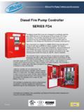
Transcription of MANUAL FOR MODEL FD4 FIRE PUMP CONTROLLERS
1 Metron, Inc. Date: 03/22/04 Approved: MH DOC#: 586 Revision: C Date: 03/27/06 Approved: MH Page: 1 of 25 MANUAL FOR MODEL FD4 FIRE PUMP CONTROLLERS Starting Serial No. "BF" This MANUAL provides General Information, Installation, Operation, Maintenance and System Set-Up Information for METRON MODEL FD-4 Engine Driven Fire Pump CONTROLLERS . TABLE OF CONTENTS PART I General Information .. PAGE 3 PART II Functions .. PAGE 3 PART III Operation of the PAGE 4 PART IV Installation & Test Procedure.
2 PAGE 5 PART V Additional Optional Features .. PAGE 8 PART VI Operator Interface Device (OID) Use and Navigation ..PAGE 9 PART VII System Set Point Definitions .. PAGE 18 PART VIII Alarm and Event Log PAGE 22 APPENDIX 1 Changing Printer Paper and Ribbon Cartridge .. PAGE 24 METRON, INC. 1505 West Third Avenue Denver, Colorado 80223 Telephone: (303) 592-1903 Fax: (303) 534-1947 Page 2 of 25 File Name: Doc# THIS PAGE IS BLANK Page 3 of 25 File Name: Doc# PART I: GENERAL INFORMATION The basic function of the MODEL FD4 Fire Pump controller for diesel engine driven fire pumps is to automatically start the engine upon a drop in pressure in the water main, or from a number of other demand signals.
3 This controller provides automatic cycled cranking, alarm and/or alarm shutdown protection for various engine failures. Stopping of the engine after the demand period is over may be either MANUAL or automatic. This controller also includes an automatic weekly test starting feature. PART II: FUNCTIONS Equipment is provided in the controller to provide the following functions: A. Automatic Starting From: a. Drop in water line pressure b. Loss of battery charger output (if enabled) c. Operation of optional remote start switches, such as remote start switch, deluge valve switch, fire alarm switch, etc.
4 D. Weekly test timer B. OID Operator Interface Device - Provided for display of alarm functions, system pressure, battery volts, battery charger amps, alarm conditions, etc. Includes buttons for Auto, Test, MANUAL and Off. Also features a 4 line by 20 character LCD for display C. Automatic Cranking - A microprocessor controlled crank cycle timer provides six (6) fixed crank periods separated by five (5) rest periods each of approximately 15 seconds duration. D. Alarms and Signal Lights - Twelve (12) Standard lights are provided to give visual signals for; "System Fault , "Battery #1 Failure , Battery #2 Failure", "Charger #1 Failure", Charger #2 Failure , AC Power Loss , Engine Running , "Engine Failed to Start", "Engine Low Oil Pressure", "Engine High Water Temp", "Engine Overspeed" and Low Fuel.
5 In addition the mode buttons have LED s on the button indicating Auto , MANUAL , Test , or Off mode. 12 additional lights, configurable by the factory, are provided for "Pump Room Alarms". An audible alarm horn is mounted on the front of the cubicle for sounding in the event of failure. Terminals are provided for remote failure indication of the following: "Automatic Mode" "System Fault" "Engine Running (2 sets)" "Common Battery Fault" E. A data logger is provided as standard to record system pressure along with numerous alarm conditions and system events.
6 The data can be displayed on the OID or can be downloaded to a PC through the RS232 port provided on the main system board or printed to the internal printer (if supplied). F. A weekly test timer is supplied to automatically start the engine any set day of the week, at a set time of day, and a preset run time. See System Config Screen 106. G. "Stop" Pushbutton - A pushbutton is provided to stop the engine in Automatic only after starting causes have returned to normal. This returns the controller to the automatic position. H. Integral Battery Chargers (Option J).
7 There are two separate fully automatic, solid state chargers provided for maintaining full charge on the dual sets of engine batteries. An LED display is provided on the charger circuit board with a selector switch for reading the charging current and voltage on each charger as standard. I. Cabinet - A heavy gauge steel cubicle encloses the controller . The OID, battery circuit breakers, and MANUAL start pushbuttons are mounted behind a break-glass in the door of the cabinet. Page 4 of 25 File Name: Doc# PART III: OPERATION OF THE controller A.
8 When the controller is the "Auto" mode and both circuit breakers are in the "On" position, the controller is in standby condition ready to start the engine automatically. A green pilot light above the "Auto" button will illuminate in this mode. Also, Battery #1 Fault and Battery #2 Fault lights should be off indicating that battery power is available. When the water pressure drops below a level which is set in System Config Screen 101, the controller will actuate the starter motor and the cranking cycle will commence. If the engine starts and runs, cranking will cease and the protective circuits will be operative.
9 If the engine fails to start after six (6) crank periods, cranking will cease, the "Engine Failed to Start" light will illuminate, and the alarm horn will sound. The battery alternating circuit alternates batteries on each crank attempt unless one battery is in a discharged state and incapable of cranking the engine. In this instance, the control will lock onto the other battery for the remaining cranking attempts. Dry contacts for remote indication of "Battery Failure/Missing Battery" are provided. The panel is wired so that optional remote start switches may be used, such as Deluge Valve, Remote Start pushbutton, Fire Alarm switches, etc.
10 In addition, when Power Failure Engine Startup feature is enabled (System Config Screen 111), the controller will automatically start the engine upon loss of Battery Charger output or AC Power loss, after an adjustable time delay (System Config Screen 112). While the engine is running, all protective circuits are operative. If the engine stops while running, and there is still an auto start demand, the control will attempt to restart the engine. If the engine fails to start the "Engine Failed to Start" light will illuminate and the alarm will sound.