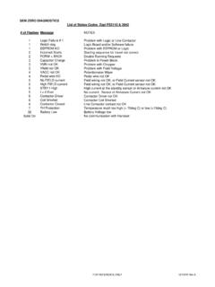
Transcription of MANUAL - FSIP
1 MANUAL 1999 CURTIS INSTRUMENTS, OF CURTIS PMC 1200 SERIESCONTROLLERS PROTECTED BY NO. motor CONTROLLERS1207 / 1207A Manualp/n 16081, Rev. D: August 1999 CURTIS PMC235 East Airway BoulevardLivermore, California 94568 USATel: 925-961-1088 Fax: / 1207A Manualp/n 16081, Rev. D: August 1999 1999 CURTIS INSTRUMENTS, electronic version of the 1207/1207A MANUAL is offered as a convenience to ourcustomers. You may download any or all of you would like a hard copy of the published MANUAL , please order it by part number fromthe Curtis office nearest electronic version of the MANUAL is identical to the printed version published in August1999 and revised March 2000. The revisions are in Figures 4, 4A, and 9A (on pages 8, 24,and 28).Bookmarks have been added to the electronic version to speed the process of goingdirectly to a particular part of the INSTRUMENTS, KISCO AVENUEMOUNT KISCO, NEW YORK 10549 USA 914-666-2971 FAX914-666-2188 CURTIS PMC235 EAST AIRWAY BOULEVARDLIVERMORE, CALIFORNIA 94550 USA 925-961-1088 FAX925-961-1099 ADDITIONAL OFFICES located inBulgaria, China, England, France, Germany,India, Italy, Japan, Netherlands, Puerto Rico,Russia, Sweden, and SwitzerlandCurtis PMC 1207/1207A.
2 AND WIRING: 1207 controllers .. 31207 Mounting .. 31207 Connections: Low Current .. 41207 Connections: High Current .. 51207 Adjustment Panel .. 51207 Wiring: Standard Configuration (Series motor ) .. 6 Power wiring for series motor .. 7 Control wiring for series motor .. 71207 Wiring: Compound motor Configuration .. 8 Power wiring for compound motor .. 9 Control wiring for compound motor .. 91207 Wiring: Throttle .. 105k 0 throttle ( Type 1 ) .. 100 5V, 0 10V, 3-wire potentiometer, andelectronic throttles ( Type 2 ) .. 110 5k throttle ( Type 3 ) .. 151207 Wiring: Emergency Reverse Check .. 151207 Switches and Other Hardware .. 16 Keyswitch .. 16 Main contactor .. 16 Forward/reverse contactors .. 16F/R and emergency reverse switches .. 16 Circuitry protection devices .. 161207 Installation Checkout .. 172A. INSTALLATION AND WIRING: 1207A controllers .. 191207A Mounting .. 191207A Connections: Low Current .. 201207A Connections: High Current .. 211207A Wiring: Standard Configuration (Series motor ).
3 22 Power wiring for series motor .. 23 Control wiring for series motor .. 23 CONTENTSC urtis PMC 1207/1207A ManualivCONTENTS123456789012345678901234 5678901234567890123456789012345678901234 5678901234567890123456789012345678901234 5678901234567890123456789012345678901234 5678901234567890123456789012345678901234 5678901234567890123456789012345678901234 5678901234567890123456789012345678901234 5678901234567890123456789012345678901234 5678901234567890123456789012345678901234 5678901234567890123456789012345678901234 5678901234567890123456789012345678901234 5678901234567890123456789012345678901234 5678901234567890123456789012345678901234 5678901234567890123456789012345678901234 5678901234567890123456789012345678901234 5678901234567890123456789012345678901234 5678901234567890123456789012345678901234 5678901234567890123456789012345678901234 5678901234567890123456789012345678901234 5678901234567890123456789012345678901234 5678901234567890123456789012345678901234 5678901234567890123456789012345678901234 5678901234567890123456789012345678901234 5678901234567890123456789012345678901234 5678901234567890123456789012345678901234 5678901234567890123456789012345678901234 5678901234567890123456789012345678901234 5678901234567890123456789012345678901234 5678901234567890123456789012345678901234 5678901234567890123456789012345678901234 5678901234567890123456789012345678901234 5678901234567890123456789012345678901234 5678901234567890123456789012345678901207 A Wiring: Compound motor Configuration.
4 24 Power wiring for compound motor .. 25 Control wiring for compound motor .. 251207A Wiring: Throttle .. 265k 0 throttle ( Type 1 ) .. 260 5V, 0 10V, 3-wire potentiometer, andelectronic throttles ( Type 2 ) .. 270 5k throttle ( Type 3 ) .. 291207A Wiring: Emergency Reverse Check .. 291207A Switches and Other Hardware .. 30 Keyswitch .. 30 Main contactor .. 30 Forward/reverse contactors .. 30F/R and emergency reverse switches .. 30 Circuitry protection devices .. 301207A Installation Checkout .. OF PARAMETERS .. 33 Electronic Adjustment, via the Programmer .. 33 Mechanical Adjustment, via the Trimpots (1207 only) .. 35 Cleaning .. 35 Diagnostic History .. 35 Testing the Fault Detection Circuitry .. AND TROUBLESHOOTING .. 37 LED Diagnostics .. 37 Programmer Diagnostics .. OPERATION .. 40 Operating Modes .. 42 Peace-of-Mind Programming .. 45 Progammer Menus .. 46 APPENDIX AGlossary of Features and Functions .. A-1 APPENDIX BSpecifications; Auxiliary Panels.
5 B-1 Curtis PMC 1207/1207A ManualvFIGURESFIG. 1: Curtis PMC 1207 and 1207A motor controllersand handheld programmer .. 1 FIG. 2: Mounting dimensions,Curtis PMC 1207 controller .. 3 FIG. 3: Standard wiring diagram (series motors),Curtis PMC 1207 controller .. 6 FIG. 4: Compound motor wiring diagram,Curtis PMC 1207 controller .. 8 FIG. 5: Wiring for 5k 0 throttle (1207 controller) .. 10 FIG. 6: Wiring for 20k potentiometerused as a wigwag-style throttle (1207 controller) .. 10 FIG. 7: Wiring for 0 5V throttle (1207 controller) .. 11 FIG. 8: Wiring for 0 10V throttle (1207 controller) .. 12 FIG. 9: Wiring for 3-wire pot throttle (1207 controller) .. 13 FIG. 10: Wiring for Curtis ET-XXX electronic throttle(1207 controller) .. 14 FIG. 11: Wiring for 0 5k throttle (1207 controller) .. 15 FIG. 2A: Mounting dimensions,Curtis PMC 1207A controller .. 19 FIG. 3A: Standard wiring diagram (series motors),Curtis PMC 1207A controller.
6 21 FIG. 4A: Compound motor wiring diagram,Curtis PMC 1207A controller .. 24 FIG. 5A: Wiring for 5k 0 throttle (1207A controller) .. 26 FIGURESC urtis PMC 1207/1207A ManualviFIG. 6A: Wiring for 20k potentiometerused as a wigwag-style throttle (1207A controller) .. 26 FIG. 7A: Wiring for 0 5V throttle (1207A controller) .. 27 FIG. 8A: Wiring for 3-wire pot throttle (1207A controller) .. 28 FIG. 9A: Wiring for Curtis ET-XXX electronic throttle(1207A controller) .. 28 FIG. 10A: Wiring for 0 5k throttle (1207A controller) .. 29 FIG. 11A: Alternative wiring for emergency reverse check(1207A controller) .. 29 TABLESTABLE 1: LED codes .. 37 TABLE 2: Troubleshooting chart .. 39 FIGURES/TABLESC urtis PMC 1207/1207A Manual111 OVERVIEWOVERVIEWC urtis PMC 1207/1207A programmable motor speed controllers provide effi-cient, cost-effective, and simple-to-install control for a variety of small electricvehicles. Typical applications include walkie fork/pallet trucks, mini personnelcarriers, and sweepers.
7 The microprocessor-based logic section combined with aproven MOSFET power section gives the 1207/1207A controllers high powerand advanced features in a simple, compact package. The optional handheldprogrammer enables the user to set parameters, conduct tests, and obtain diag-nostic information quickly and 1 Curtis PMC1207 and 1207 Aelectronic motor controllersand handheld all Curtis PMC motor controllers, the 1207 and 1207A models offersuperior operator control of the vehicle s motor drive speed. Features include: Power MOSFET design, providing infinitely variable drive and plug brake control silent high-frequency operation high efficiency (for reduced motor and battery losses) Compact size Overvoltage and undervoltage protection Thermal protection and compensation circuitry provides undertemperaturecutback, constant current limit, and linear rollback in overtemperature thus preventing sudden power loss regardless of thermal conditions More FeaturesCurtis PMC 1207/1207A Manual2 Intelligent handheld programmer (optional) provides a full set of parameterand function settings Diagnostic and test information for the controller and other system com-ponents readily available both on-board and through the programmer On-board potentiometers allow direct MANUAL adjustment of accelerationrate, creep speed, maximum speed, plug current, and main current limit(1207 single-mode models only)
8 Circuitry and software detects faults in the throttle circuit, MOSFET drivecircuit, MOSFET transistors, contactor drivers, and contactors ensuringthat the controller meets EEC fault detect requirements Input sequencing options include neutral start and static return to off (SRO) Microprocessor-controlled contactor sequencing provides true arclesscontactor switching Smooth, controlled plug braking with either variable (throttle-dependent)or fixed plug current limit Neutral braking option provides automatic plug braking in neutral MultiMode input selects between two different operating modes, thusallowing optimization of vehicle characteristics for different driving condi-tions Emergency reverse (belly button switch) with a single input Ramp-start feature provides full power for starting on ramps Simple contactor and switch wiring, with coil drivers monitored for faults thus ensuring fail-safe operation Flexible throttle circuitry accommodates a variety of throttle types Programmable ramp shape (static throttle map) provides flexibility inselecting throttle response feel Connections made by solid copper power busses with a polarized Molexconnector for control signals Solid, well-protected construction with an aluminum mounting plate andinjection-molded with your Curtis PMC controller will help you install and operate itproperly.
9 We encourage you to read this MANUAL carefully. If you have questions,please contact the Curtis office nearest OVERVIEWC urtis PMC 1207/1207A Manual3 INSTALLATION AND WIRING: 1207 MOUNTINGThe 1207 controller can be oriented in any position, but the location should becarefully chosen to keep the controller as clean and dry as possible. If a cleanmounting location cannot be found, a cover must be used to shield thecontroller from water and ensure full rated output power, the controller should be fastened to aclean, flat metal surface with three screws. The case outline and mounting holedimensions are shown in Figure 2. The controller should be mounted withsufficient clearance to allow the sliding cover to be opened, providing access to22 INSTALLATION & WIRING: 1207 Controller66 ( )28 ( )122( )152 ( )165 ( )127 ( ) ( )22 ( )60( ) ( )21 16 ( ); ( ) dia. hole ( ) dia.,3 plcsDimensions in millimeters and (inches)CLFig.
10 2 Mountingdimensions,Curtis PMC PMC 1207/1207A Manual4the user-adjustable potentiometers. Access is also needed to plug the programmerinto the connector beneath the sliding cover, and to view the Status not usually necessary, a thermal joint compound can be used toimprove heat conduction from the case to the mounting :Low CurrentAn integrated 16-pin low power connector molded into the front of the control-ler provides the low power logic control connections (see pin list below). Themating connector is Molex Mini-Fit Jr., part number (5557) Molex regarding compatible pins for various wire INSTALLATION & WIRING: 1207 ControllerPin 1shunt field driver output; n/c for series motorsPin 2reverse contactor driver outputPin 3forward contactor driver outputPin 4main contactor driver outputPin 5throttle: 3-wire pot highPin 6throttle: 3-wire pot wiper or 0 5 VPin 7throttle: pot lowPin 8throttle: 2-wire 5k 0 or 0 5k inputPin 9throttle: 0 10 VPin 10emergency reverse (BB) check output [optional]Pin 11reverse inputPin 12forward inputPin 13emergency reverse inputPin 14mode selection inputPin 15brake inputPin 16keyswitch input (KSI)16151413121110987654321 Curtis PMC 1207/1207A Manual5 CONNECTIONS: High CurrentFour tin-plated copper bus bars are provided for the high current connections tothe battery and motor .