Transcription of Manual Lever/Cam/Plunger Operated Directional …
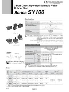
1 Manual Lever/Cam/Plunger Operated Directional Valve DG3/17/18/20/21-3 60 Design eaton Directional valves offer These valves are rated at Hydraulic Pilot Operated Low shock characteristics versatility of application for flows to 75 l/min (20 USgpm) Available in an NFPA D03 to maximize machine life the many Directional control and 350 bar (5000 psi) interface. valves are rated at Choice of five types requirements of hydraulic maximum pressure. Roller flows to 151 l/min of control to satisfy machinery. Ruggedness cam, plunger, spring offset, (40 USgpm) and maximum applications where of design, manufacturing detented, spring centered, pressure of 350 bar electrical control is not quality, and worldwide knob or lever Operated (5000 psi) appropriate parts and service availability models are available. maximize uptime, resulting Feature and Benefits in greater profits for your Air Operated High pressure and flow company. Available in an NFPA D03 capability for maximum interface with rated flows cost effectiveness Manual Lever/Cam/Plunger to 75 l/min (20 USgpm) and valves Low head loss to minimize E maximum pressure of 350.
2 These valves are available power loss bar (5000 psi). in an NFPA D03 interface. DG3V 3 * 60. DG18V 3 * 60 Hydraulic Operator Air Operator DG17V 3 * 60. Lever Operator DG21V 3 * 60. Plunger Operator DG20V 3 * 60. Cam Operator E-2 eaton DG3/17/20/21/18V-3-10 Design E-VLVI-SS001-E1 October 2015. General Information General Description Manual lever and cam spring centered; 2 position the valve spool. No-spring operations must be released detent; 2 position spring (offered as pilot valves for Five types of valve are from their actuated positions, offset to port A, B operator; no-spring detented models available with different without any restrictions to 2 position spring offset to port only) require only momentary controls primarily for spring return. B, A operator. pressurization of pilot port controlling the starting, Cam Operated Directional Note: to shift spool (approx. stopping and direction of fluid control valve installation seconds). flow in a system. Manual actuator in end cap feature recommendations: (P2) available on single operator When pilot pressure is The valves are developed Maximum cam angle 35 models only.
3 In right hand assembly, relieved, spool will remain in from the well-known series operator A is always removed. In last position attained provided of DG4V-3-60 series solenoid Cam travel for dead band left hand assembly, operator B is there is no severe shock, Operated valves (see eaton of 9 30' on either side of always removed. See identification vibration or unusual pressure literature # GB-C-2015). center for closed center plate on top of valve for operator transients. These Manual valves are spools for 35 cam. available with a choice of (port) identification. Note: up to nine different spool This dead band should be For every 3,3 bar (50 psi). E. taken into consideration Surges of oil in a common tank line types, depending on valve increase in tank line pressure serving these and other valves can configuration. All spools when designing cam and system circuits. the air pilot pressure must be of sufficient magnitude to cause have been designed to be increased bar (1 psi). inadvertent shifting of these valves .
4 Provide good low-shock Cam should not drive roller Maximum tank line pressure This is particularly critical in the characteristics. External at its vertical centerline to is 100 bar (1450 psi). no-spring and no-spring detented regulation of the control avoid any side loading on type valves . Separate tank lines or a input by hydraulic, lever, roller lever mechanism. Nameplate identification label is asymmetrical and fixes vented manifold with a continuous pneumatic, cam or plunger downward path to tank is preferred. operation allows matching Actuation Force the A and B operators to virtually any requirement in relation to the P port. Any sliding spool, if held Under rated conditions*, the Designers should note for shifted under pressure for where electrical control is not approximate actuation force installation on vertical panels. long periods of time, may appropriate. will be as shown in the chart stick and not spring return Models include no-spring, On all right hand models, below: due to fluid residue formation spring offset, spring centered when operator A is Valve type Force Nm (lbf.)
5 *. pressurized, flow is always P (silting) and therefore, should and detented versions. DG17V-3-*A 22 - 31 (5 to 7) be cycled periodically to to A. When operator B is DG17V-3-*C 13 - 22 (3 to 5) pressurized, flow is always prevent this from happening. DG3V-3-*-60 Hydraulic Operated DG17V-3-*N 22 - 31 (5 to 7) P to B. Operators A and If this valve is used for DG17V-3-*A 53 - 62 (12 to 14) B are identified on the purposes other than a 4-way The hydraulic Operated DG3V- DG17V-3-*C 45 - 53 (10 to 12) identification plate on top valve or as shown in the 3-*-60 Directional valves are of the valve. For left hand graphical symbol on the valve, DG17V-3-*A 100- 250 (22 to 56). used to control the direction assembly this is reversed consult your distributor or of flow in a hydraulic circuit, *Tank return must be designed so (P to B when the A sales engineer. which would control the that transient tank line pressure operator is pressurized). movement of a work cylinder peake do not exceed 6,9 bar (100 Mounting Position or the rotation of a fluid psi).
6 For tank return line pressure Shift Time motor. in excess of 6,9 bar (100 psi) lever There is no restriction on movement must be assisted. Shift time is essentially mounting of spring centered DG**V-3-*-60 Lever/Cam/ dependent upon pilot or spring offset models. Note: pressure, line length and Detented models must be Plunger Operated In right hand assembly, operator diameter, and speed of mounted with the spool Operating Information A is always removed. In left control mechanism. Spring bore horizontal to reduce the The DG21V-3 plunger hand assembly, operator B is return time from the possibility of accidental spool operator valves are internally always removed. Please note offset to center position shift due to shock and/or drained to port T. They may that European designations are is approximately 45 msec. vibration. be used only when surges the opposite. See diagram on the at rated flow and pressure or back pressure in the tank nameplate of the valve for operator assuming minimal back Port Connections line cannot overcome the (port) identification.
7 Pressure in the pilot line. Port connections are made force applied to depress the by mounting the valve on a plunger. DG18V-3-**-60 Air Shifting Action manifold or subplate having Operated DG17/20/21 models must Spring centered and spring mounting dimensions which be released from actuated eaton air Operated offset types will be spring conform to NFPA D03. positions, without restriction DG18V-3-**-60 Directional positioned unless sufficient (ISO-4401-03) configurations. to ensure proper spring control valves come in four pilot pressure is maintained return. basic versions: 3 position at pilot port to shift and hold eaton DG3/17/20/21/18V-3-10 Design E-VLVI-SS001-E1 October 2015 E-3. Model Code D G 3 V - 3 ** * (*) - (*) - (*) - * - * - 60. 1 2 3 4 5 6 7 8. 1 Valve Type N No-spring detent B SAE internal straight 3 Hydraulically Operated threads V 350 bar (5000 psi) on 4 Internal Drain P, A & B ports (omit if not required) 8 Design 3 ISO 4401-03 (CETOP A, B & F models only for Installation dimensions 3,NFPA D03) ISO designs (F models must remain as shown for design 4401-AB-03-4-B have internal drain) numbers 60 thru 69.
8 T Internal drain E 2 Spool Type Refer page 6 for spool type 5 Manual Override Option 3 Spool Spring A, B & F models in Arrangement non-operator end A Spring offset, end-to- P1 Manual override end AL Same as A but left 6 Tank Pressure Limit hand build B Spring offset, end to 7 210 bar (3000 psi). center 7 Thread for Pilot/Drain BL Same as B but left Connection hand build C Spring centered P G1 8 NPT threads D G ** V - 3 - * * (*) * - 60. 1 2 3 4 5. 1 Valve Type end numbers 60 thru 69. * Operator AL Same as A but left 17 Lever Operated hand build 20 Roller cam B Spring offset, end to Operated center 21 Plunger operater BL Same as B but left V 350 bar (5000 psi) on hand build P, A & B ports C Spring centered 3 ISO 4401-03 (CETOP N No-spring detent 3,NFPA D03) ISO. 4401-AB-03-4-B 4 Tank Port Rating Omit if not required 2 Spool Type 2 10 bar max for DG21V. Refer page 7 for spool type only 3 Spool Spring 5 Design Arrangement Installation dimensions A Spring offset, end-to- remain as shown for design E-4 eaton DG3/17/20/21/18V-3-10 Design E-VLVI-SS001-E1 October 2015.
9 Model Code D G 18 V - 3 - * * (*) - (**) - (*) - * - 60. 1 2 3 4 5 6 7. 1 Valve Type FL Spring offset, shift Note: Type 8 spool conforms to 18 Air Operated to center, build both methods. All type 8 spools V 350 bar (5000 psi) on (single operator) must designate V in model code. P, A & B ports N No-spring detented 3 ISO 4401-03 (CETOP. 6 Pilot Source Thread 3,NFPA D03) ISO. 4 Manual Override Connections 4401-AB-03-4-B. Option P 1 8 NPT threads (Applicable for A(L), B(L) & B 1 8 BSP threads 2 Spool Type (center E. F(L) models only). condition). Blank Overrides in Refer page 8 for spool type 7 Design operator end only P2 Override in both ends of Installation dimensions 3 Spool Spring single operators remain as shown for design Arrangement numbers 60 thru 69. A Spring offset to A, (single operator) 5 Actuator Identity AL Spring offset to B, Blank Standard build (single operator) arrangement ( B Spring centered, apply air to operator operator A removed A to give flow P to (single operator) A) (Ref.)
10 US ANSI. BL Spring centered, ). operator B removed V Operator identification (single operator) determined by position C Spring centered (dual of operator ( operator operator) A at A port end of valve F Spring offset, shift to operator B at B port end center (single operator) of valve). eaton DG3/17/20/21/18V-3-10 Design E-VLVI-SS001-E1 October 2015 E-5. Functional Symbols Spool Options for DG3V-3-60. Spool Options Model Basic Valve Symbol Usable Spool Options b o a A B. 0 DG3V-3-** 0, 2, 6 & 22. b a P T. A B. 2. DG3V-3-**A b a 0, 2, 6 & 22. P T. A B. 3. DG3V-3-**A-T b a 0, 2, 6. P. T. 6 A B. E DG3V-3-**B b a 0, 2, 3, 6 & 33. P T. 22 A B. DG3V-3-**B-T b a 0, 2, 3, 6 & 33. P. T. 33 build only A B. DG3V-3-**C b o a 0, 2, 3, 6 & 33. P T. A B. DG3V-3-**F-T b a 0, 2, 3, 6 & 33. P. T. build only A B. DG3V-3-**N b o a 0, 2, 6. P T 123. Single operator models marked are optionally available with a Manual override in the non-operator end only. Models with operators at both ends are not available with Manual overrides.