Transcription of MANUAL METAL ARC (MMA) “STICK” WELDING - …
1 AN INTRODUCTION TO MANUAL METAL ARC (MMA) stick WELDING wws group | WARNING: This document contains general information about the topic discussed herein. This document is not an application MANUAL and does not contain a complete statement of all factors pertaining to that topic. The installation, operation and maintenance of arc WELDING equipment and the employment of procedures described in this document should be conducted only by qualified persons in accordance with applicable codes, safe practices, and manufacturers instructions. Always be certain that work areas are clean and safe and that proper ventilation is used. Misuse of equipment, and failure to observe applicable codes and safe practices can result in serious personal injury and property damage. an introduction to MMA stick WELDING page 2 of 11 | Introduction Arc WELDING with coated electrodes is a MANUAL process where the heat source consists of the electric arc.
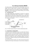
2 When the arc strikes between the coated electrode (by means of an electrode holder) and the piece to be welded (base material), it generates heat which causes rapid melting of both the base material and electrode. The WELDING circuit consists essentially of the following elements: a power source an electrode holder coated electrodes an earth clamp and earth cables as illustrated in figure 2 below. The Power Source The purpose of the power source is to feed the electric arc, which is present between the base material and the electrode, through the output of a current sufficient in quantity to keep the arc struck. Electrode WELDING is based on the constant current principle the current delivered by the power source should not vary when the operator moves the electrode towards the piece. The main construction property of the source is therefore to keep the current unchanged in the presence of variations in arc length as the electrode moves closer to or away from the piece: the more constant the current, the more stable results the arc and the simpler the operator's work.
3 Inside the power source, there is usually a WELDING current adjustment device, of a mechanical ( a magnetic shunt) or electronic type (SCR systems or inverter systems). This distinction can be used to classify electrode WELDING machines into three families, depending on their construction technology: electromechanical WELDING machines, electronic WELDING machines (SCR), inverter WELDING machines. The polarity of the power source output current distinguishes two further categories: a) direct current (DC) power source (see figure 3) The power source output current has a continuous wave form, which is obtained by means of a device, the rectifier, which is situated at the base of the transformer and can convert from alternating to direct current. This output is typical of electronic SCR and inverter power sources. If the WELDING circuit has a direct current (DC) power source, it can be further classified according to the method of connecting the power source poles to the material to be welded: b) alternating current (AC) power source (see figure 4) The power source output current takes the form of a sine wave, which changes its polarity at regular intervals, with a frequency of 50 or 60 cycles per second (Hertz).
4 It is obtained using a transformer, which converts the mains current into a suitable current for WELDING . This is for electromechanical WELDING machines. i) straight polarity connection Straight polarity connection occurs when the clamp cable (with the electrode holder clamp) is connected to the negative pole (-) of the power source and the earth cable (with the earth clamp) to the positive pole (+) of the power source. The electric arc concentrates the heat produced on the piece and causes its melting. In this way, as the core of the electrode melts, it is deposited and penetrates into the WELDING joint. figure 1 figure 2 figure 3 figure 4 an introduction to MMA stick WELDING page 3 of 11 | ii) reverse polarity connection Reverse polarity connection occurs when the clamp cable (with the electrode holder clamp) is connected to the positive pole (+) of the power source and the earth cable (with the earth clamp) to the negative pole (-) of the power source.
5 The heat of the electric arc is mostly concentrated at the tip of the electrode. Each type of electrode requires a specific current type (AC or DC) and, in the case of DC current, a specific polarity: the choice of the electrode therefore depends on the type of power source used. Incorrect use will cause arc stability problems and hence also WELDING quality problems. electrode holder The primary function of the electrode holder is to support the electrode, guaranteeing a good electrical contact for current passage; it should also guarantee sufficient electrical insulation for the WELDING operator. earth clamp and cables The earth clamp is a tool that, via the earth cable, ensures the electrical circuit is closed between the WELDING power source and the piece to be welded. The clamp and earth cables, connected to the electrode holder and earth clamp respectively, permit an electrical connection between the power source and the base material to be welded.
6 The choice of cable section and length should be based on the maximum WELDING current in amps. coated electrodes The coated electrode consists of a core and a coating. The core consists of a METAL conductor rod whose sole purpose is to supply WELDING material to the piece. The material used depends on the base material: for carbon steels, for which electrode WELDING is most widespread, the core is in mild steel. During WELDING the core melts slightly before the coating does. The coating is the most important part of the electrode and has many functions. It primarily serves to protect the weld from contamination, and it achieves this in two ways: i) By volatilizing, and then modifying the atmosphere surrounding the weld pool by delay melting, the core is consequently protected by the naturally formed crater; ii) by liquefying and floating on top of the pool, the bead is protected as it cools. It also contains material capable of purifying the base material and elements that could contribute to the creation of alloys in the melt.
7 The choice of coating is therefore very important and depends on the characteristics to be given to the weld. The coating can also contain weld material as a powder, to increase the quantity of deposited material and hence the WELDING rate. In this case we refer to high performance electrodes. modern power source features Modern inverter WELDING power sources may contain special features whose functions are to facilitate easier WELDING . These devices can include arc force , hot start and anti- stick technology. An arc force device eases the transfer of drops of melted material from the electrode to the base material, preventing the arc from extinguishing when the drops cause contact ( a short circuit) between the electrode and the weld pool. A hot start device facilitates the striking of the electric arc, by supplying an over-current every time WELDING restarts. An anti- stick device automatically switches off the power source if the electrode sticks to the base material, thus allowing it to be removed manually without ruining the electrode holder clamp.
8 Figure 7 figure 6 figure 5 an introduction to MMA stick WELDING page 4 of 11 | General Principles Shielded METAL -arc WELDING with the transformer WELDING machine depends upon the fundamental fact that when one side of the WELDING circuit is attached to a piece of steel, a WELDING electrode connected to the other side and the two brought into contact, an arc will be established. If the arc is properly controlled, the METAL from the electrode will pass through the arc and be deposited on the steel. When the electrode is moved along the steel at the correct speed, the METAL will deposit in a uniform layer called a bead. The electrodes used in WELDING are carefully manufactured to produce strong, sound welds. They consist of a core of steel wire, usually called mild since it contains a low ( ) percentage of carbon. Around this core is applied a special coating which assists in creating the arc and at the same time protects the molten steel as it transfers across the arc.
9 In order to utilize these principals in METAL -arc WELDING , some means of controlling the power is essential. The power in a circuit is measured by the voltage and current. However, the voltage is governed by the arc length and in turn depends on the electrode diameter. Therefore, the practical measure of the power, or heat, is in terms of the current, generally measured in amperes. Obviously a small electrode requires less current than a large one. To simplify operations the scale on the front of the WELDING machine is marked off for the various current values. The exact current selected for a job depends upon the size of the pieces to be welded and the position of WELDING . Generally a lower current will be sufficient for WELDING on a small part than would be necessary to weld on a large piece of the same thickness. Similarly, with a given size of electrode a lower current should be used on thin metals than on the heavier sections. While it is always a good policy to weld on work in the flat position, as shown in figure 8, occasionally, when working on machines or other large units it will be necessary to weld in a vertical, horizontal or overhead position as shown in figures 9, 10 and 11 respectively.
10 Generally, under these difficult conditions it is helpful to reduce the current from the value used on WELDING in the flat position. In learning to weld there are certain fundamental steps, which must be mastered before one can attempt to weld on actual work. Preparatory to the actual striking of an arc, it is necessary to insert the electrode in the holder, as shown in figure 12. Arc Ignition For striking an arc, figure 13 illustrates what is commonly known as the scratching technique . In this method the striking end of the electrode is dragged across the work in a manner much the same as striking a match. When the electrode touches the work, the WELDING current starts. If held in this position, the electrode would figure 9 figure 8 figure 10 figure 11 figure 12 an introduction to MMA stick WELDING page 5 of 11 | freeze or weld itself to the work and to overcome this, the electrode is withdrawn from the work immediately after contact has been made.