Transcription of Manual ultrasonic inspection of thin metal welds
1 Manual ultrasonic inspection of thin metal welds Capucine Carpentier and John Rudlin TWI Cambridge CB1 6AL, UK Telephone 01223 899000 Fax 01223 890689 E-mail Abstract BS EN ISO 17640 contains standard ultrasonic inspection techniques for ferritic steel welds . The techniques in general include scans with different angles from either side of the weld . The minimum thickness noted in this standard is 8mm. However there are an increasing number of applications involving smaller thicknesses ( , containments) and these cannot strictly be inspected by these methods. This paper describes a series of experiments of conventional ultrasonic and phased array testing on thin butt welded sections with simulated flaws using the procedures described in BS EN ISO 17640 and BS EN 13588 but allowing the use of high frequency and small probes easily available in the market.
2 The results show that the procedures of BS EN ISO 17640 can be adapted in this way for detection scanning and sizing for thicknesses down to 4mm. 1. Introduction thin walled vessels and pipes are increasingly required to be tested non-destructively when they are used to contain substances that can damage a local environment. Examples include some designs of nuclear waste storage vessels, nuclear processing plant, low pressure oil pipes and other fuel systems. Different welding methods for stainless and duplex steel are also under investigation for these areas. Equally there is a need to determine the actual size of a remaining ligament as this has a significant effect on fracture mechanics analyses.
3 Conventional ultrasonic testing (according to BS EN ISO 17640) (1) limits thicknesses that can be examined to less than 8mm. Similarly, the draft phased array standard BS EN 13588 (2) goes down to 6mm. Smaller thicknesses are frequently inspected by radiography, this cannot normally give the through thickness information required for fracture mechanics analyses. There is a requirement for non-destructive test methods in the smaller thickness ranges. Bird (3) reported an experiment comparing Manual UT and phased array with thicknesses down to 6mm with good results for good operators using both techniques. New or different technologies, such as eddy current arrays or high frequency ultrasonic phased arrays may be needed for smaller thicknesses.
4 A special 2 case where ultrasonic methods have been developed for a thin wall has been given by Bird et al.(4) Some work on eddy currents is reported in this conference (5). However, from the manufacturers point of view it is convenient to refer to a standard when requesting items to be made, and to know what the actual limitations are of the current UT methods. The main purpose of this paper is therefore to examine whether the normal Manual ultrasonics procedures used in the standard can be applied with minimum modification to inspect arc welds in thin sections and whether phased array techniques can improve on this. The reason that the 8mm limit applies in most cases is that it is not possible with thinner sections to apply standard UT probes because they cannot approach the weld close enough nor can the beam be easily defined.
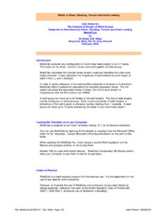
5 The modification to the standard procedure adopted is to allow the use of high frequency 10 MHz angled beam probes. Phased array technology for weld inspection is becoming mature, with a draft standard for weld inspection BS EN 13588(6), and this standard and technique were also adopted. 2. Test Samples The test samples specified consisted of plates 3, 4 and 5mm thick in ferritic and stainless steel, each containing 4 flaws. Figure 1 shows the position of these in the 4mm plate, the others were similar. The weld has a 60 preparation and there are three embedded lack of fusion flaws at the weld cap and one root lack of fusion flaw in each plate. The flaws have been made with intended dimensions and those supplied by the manufacturer, and these are used in the analysis.
6 However, it should be noted that manufacture and measurement of such flaws has some uncertainties so the results obtained must be viewed with this in mind. A radiographic inspection of these welds was performed in order to verify the length of these flaws (Table1). As expected, the radiography was not able to reliably detect lack of side wall fusion. Table 1. Results of radiographic inspection of welds Carbon steel 3mm plate 4mm plate 5mm plate Flaws A B C D A B C D A B C D Detected? N Y N N N Y N Y N Y Y N Length \ 12 \ \ \ 12 3 \ 12 15 \ Stainless steel 3mm plate 4mm plate 5mm plate Flaws A B C D A B C D A B C D Detected? Y Y N N N Y N N N Y N Y Length 7 12 \ \ \ 12 \ \ \ 12 \ 15 3 Length: 10mm Length: 10mm Length: 5mm Length: 15mm Figure 1 Position of the simulated flaws in the welds 3.
7 Manual UT Standard Requirements The international standard for the Manual ultrasonic testing of fusion-welded joints in metallic material BS EN 1714 has been withdrawn in 2010 and replaced by BS EN ISO 17640:2010. This standard is specified to be applied for the testing of fusion welded joints in metallic material of thickness greater than or equal to 8mm and where both the welded parent material are ferritic. The probe frequency specified in this standard are to be within the range 2 and 5 MHz. However, the standard allows the use of higher frequency for improving range resolution if necessary for acceptance criteria based on characterisation of indications. It is also required that at least one angle beam shall be normal or nearly normal to the weld fusion face.
8 The testing volume is to include the weld body and at least 10mm on each side of the weld to cover the heat affected zone (HAZ). The standard is open to several techniques to set the sensitivity. One of the techniques specified in the standard allows the use of reference from a distance-amplitude curve (DAC) for side-drilled holes of diameter 3mm. Reference can also be made on notches 4 of 1mm wide with a depth of 1mm only for the thickness range between 8 and 15mm and for angle beam angles larger than 70 . BS EN 17640:2010 refers to BS IS 11666:2010 for the definition of the evaluation level above which an indication will be investigated. For an acceptance level 2, which corresponds to the most common quality level, the level of evaluation is set at -14dB below reference level.
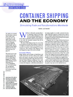
9 Equipment and Procedure The equipment used to carry out the Manual testing was a Sonatest Masterscan 380M with 10 MHz transducers 45, 60 and 70 , crystal diameter. The transducers used for the testing are shown in Figure 2. The footprints of these transducers were between 20 to 30mm and enabled the probe index point to be close to the weld cap and hence reduce the number of ultrasonic skips on the back wall. As has been mentioned above the procedures of BS17604 together with an allowance for the use of high frequency probes has been used. DAC was used relative to a 3mm SDHs. No attempt was made to have blind trials in this case. The operator had some knowledge of the flaw location and was seeking to identify and use the indication.
10 A) b) c) Figure 2 Pictures of ultrasonic transducer Parametrics A544S 10 by a) 45 wedge b) 60 wedge c) 70 wedge 4. Phased Array UT Standard Requirements The use of (semi-)automated phased array technology for the inspection of welds is covered by the draft international standard BS EN ISO 13588 which is currently open to public comments. This standard specifies the application of the phased array technology for fusion welded joints in metallic materials equal to and above 6mm thickness. 5 This standard is open to the use of linear scan (E-scan) and sector scan (S-scan) at a fixed distance to the weld to generate multi angle beam from a single position of the transducer.