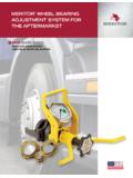
Transcription of Manual Wheel Bearing Adjustment Procedures
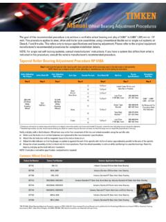
1 Manual Wheel Bearing Adjustment ProceduresPre-Adjusted Wheel Bearing Adjustment ProceduresThe goal of this recommended procedure is to achieve a verifiable Wheel Bearing end play of to (.025 mm to .127 mm). This procedure applies to steer, drive and trailer axle assemblies using conventional double nut or single nut systems on Class 6, 7 and 8 trucks. This refers only to torque specifications and Bearing Adjustment . Please refer to the original equipment manufacturer s recommended Procedures for complete installation : For single nut self-locking systems, consult manufacturers instructions. If you have a system that differs from what is indicated in this procedure, consult the vehicle manufacturer s recommended 1: Lubricate the tapered roller Bearing with clean axle lubricant of the same type used in the axle sump or hub.
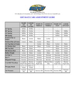
2 Never use an impact wrench when tightening or loosening lug nuts or bolts during the AdjustingNut Torque Initial Back Off Final AdjustingNut Torque Axle Type Threads Per Inch Final Back Off Nut Size TorqueSpecifications AcceptableEnd Play Step 2 Step 3 Step 4 Step 5 Step 6 Step 7 Step 8200 lbf ft(271N m)WhileRotatingWheelOneFull Turn50 lbf ft(68 N m)WhileRotatingWheelsSteer(Front)Non-Dri ve121/6 Turn*Install Cotter Pin to LockAxle Nut in - (.025 - .127 mm)As Measured Per Procedure With Dial Indicator181/4 Turn*121/3 Turn*Less Than2 5/8 ( mm)200-300 lbf ft(271-407 N m)141/2 Turn*18 Drive121/4 Turn*Dowel Type Washer300-400 lbf ft(407-542 N m)16 Tang Type Washer**200-275 lbf ft(271-373 N m)Trailer121/4 Turn*Less Than2 5/8 ( mm)300-400 lbf ft(407-542 N m)16* If dowel pin and washer (or washer tang and nut flat) are not aligned, remove the washer, turn it over and reinstall.
3 If required, loosen the inner (adjusting) nut just enough for alignment.** Bendable type washer lock only: Secure nuts by bending one Wheel nut washer tang over the inner and outer nut. Bend the tangs over the closest flat perpendicular to the Roller Bearing Adjustment Procedure RP 618 AVerify end play with a dial indicator. Wheel end play is the free movement of the tire and Wheel assembly along the spindle ) Make sure the brake drum-to-hub fasteners are tightened to the manufacturers ) Attach the dial indicator with its magnetic base to the hub or brake ) Adjust the dial indicator so that its plunger or pointer is against the end of the spindle with its line of action approximately parallel to the axis of the ) Grasp the Wheel assembly at the 3 o clock and 9 o clock positions.
4 Push the Wheel assembly in and out while oscillating it to seat the bearings. Read the Bearing end play as the total indicator : If end play is not within specification, readjustment is reasonable effort has been made to ensure the accuracy of the information contained in this writing, but no liability is accepted for errors, omissions or for any other Failure to follow these warnings could create a risk of death or serious bodily maintenance and handling practices are critical. Always follow installation instructions and maintain proper lubrication. Never spin a Bearing with compressed air. The rolling elements may be forcefully follow Wheel torque recommendations. Excessive or inadequate Wheel torque can lead to failure of the Wheel mounting system and loss of a not remove the outer Bearing once it has been installed on the spindle.
5 Removing it could cause the seal to become misaligned and lead to a seal failure or loss of a RP 618A, Wheel Bearing Adjustment Procedure, appears in TMC s 2010-2011 Recommended Practices Manual , and is published by the Technology & Maintenance Council (TMC) of American Trucking Associations; 950 N. Glebe Road, Arlington, VA 22203; (703) 838-1763; Reprinted with 0 0 12-13: 2 9 Order No. 10 420L | Timken is a registered trademark of The Timken Company. | 2012 The Timken Company | Printed in Timken team applies their know-how to improve the reliability and performance of machinery in diverse markets worldwide. The company designs, makes and markets high-performance mechanical components, including bearings, belts, chain, gears and related mechanical power transmission products and NOTE: This refers only to torque specifications and Bearing Adjustment .
6 Please refer to the original equipment manufacturer s recommended Procedures for complete installation ) Mount the hub assembly onto the axle spindle, while holding the outer cone in place. Make sure the Bearing cones, spacer and spindle are aligned to avoid seal ) Install the inner spindle nut and torque to 300 ft-lbs. Do not back off the spindle ) Engage the locking device that is part of the spindle nut system. If the locking system cannot be engaged when the nut is at 300 ft-lbs, advance the nut until the locking system can be engaged (reference note above). For a double nut or jam nut system, bend the lock tab or install the set screw after the outer nut is torqued to 200 one-piece spindle nut systems, torque the nut to a minimum of 300 ft-lbs.
7 Do not back off the spindle nut. Engage any locking device that is part of the spindle nut system. If the locking device cannot be engaged when the nut is at 300 ft-lbs, advance the nut until engagement takes place and the nut is locked.