Transcription of MARINE DIESEL ENGINES 6LPA-STP2 Series - Yanmar
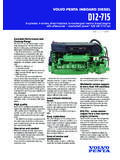
1 MARINE DIESEL ENGINES . MARINE DIESEL ENGINES . 6 LPA- stp2 Series Configuration 4-stroke, vertical, water-cooled DIESEL engine Maximum output at crankshaft * 232 kW@3800 rpm [315 mhp@3800 rpm]. 6 LPA- stp2 [299 Series ** 220 kW@3800 rpm mhp@3800 rpm]. Displacement ltr [254 cu in]. Configuration 4-stroke, vertical, water cooled DIESEL engine Bore x stroke 94 mm x 100 mm [ in x in]. Maximum output at crankshaft * 232 kW (315 mhp) / 3800 rpm ** 225 kW (306 mhp) / 3800 rpm Cylinders 6 in line, 4-valves per cylinder Continuous rating output at crankshaft Combustion system 211 kW ( mhp) / 3682 rpm Direct injection Displacement Aspiration L (254 cu in). Turbocharged with intercooler Bore x system Starting stroke 94 mm x 100 mm ( in x in). Electric starting 12V - kW. Cylinders Alternator 6 in line cylinders, 12V4-valves - 80A per cylinder Combustion Cooling system system Direct injection Fresh water cooling by centrifugal fresh water pump and Aspiration Turbocharged with intercooler rubber impeller seawater pump Starting system Lubrication system Electrical starting 12 V - Enclosed, kW lubricating system forced Alternator Direction of rotation [crankshaft] 12 V - 80 A Counterclockwise viewed from flywheel side Cooling Dry weightsystem without gear Fresh water cooling by centrifugal fresh water pump[899.]
2 408 kg and rubber lbs] impeller seawater pump Lubrication system Environmental Enclosed, forced lubricating EU: RCD system BSO II EMC. Direction of rotation (crankshaft) Counter clockwise US: viewed from flywheel side EPA Tier2. Dry weight without gear 408 kg (899 lbs)IMO: MARPOL 73/78 Annex VI. Environmental engine mounting EU RCD, US EPA Tier2,type Rubber BSOflexible II, EMCmounting & Marpol 73/78 Annex VI. engine mounting Rubber type flexible mounting NOTE: Fuel condition: Density at 15 C = g/cm ; 1 kW = mhp = HP. NOTE: Fuel condition: Density at 15 C = g/cm ; 1kW = mhp = HP. * Fuel temperature * Fuel temperature25 C at at 25 C thethe inlet inletofofthe thefuel fuelinjection injection pump pump [ISO 3046-1]. (ISO 3046-1). ** Fuel temperature ** Fuel temperature40 C at at 40 C the inlet the inletofofthe thefuel fuelinjection injection pump pump [ISO 8665: 2006]. (ISO 8665). Technical data Technical is according data to to is according ISO. ISO8665: 86652006/3046-1. / 3046. Dimensions (For detailed line-drawings, please refer to our web-site: ).
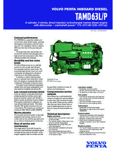
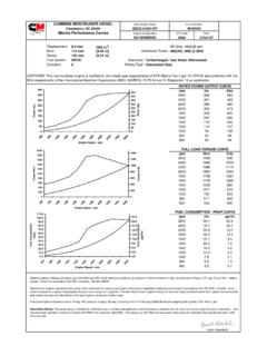
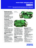
3 Dimensions Rear view Right side view mixing elbow o 102. 666 mm ( in). in). in). m ( ( riser mixing elbow (option). ). 2in 345 mm 321 mm (5. ( in) ( in). mm 55 m m 1m 15 . 260 mm 13. ( in). mm ( in). 132 mm 333 mm ( in). 389 mm ( in). 502 mm ( in). 739 mm ( in). mm ( in) 47 mm mm ( in) ( in). ( in). 237 mm mm ( in). ( in). 32 mm ( in). 8 mm mm ( in). mm (0. ( in)..3 in). 287 mm 287 mm mm EN_DS6 LPA-STP2_1214. (11,3 in) (11,3 in) ( in). 1220 mm (48 in). 6 LPA- stp2 with KM2P-1 MARINE gear 6 LPA- stp2 / KMH50A MARINE gear Performance Performance Curves Curves Performance Curves(Output is according (Output ISOISO. is according 8665). 8665). Performance Curves (Output is according ISO 8665). Power Torque Torque FuelFuel Consumption Consumption 250 800 800. Torque 70. 70 Fuel Consumption mhp 250 18 18. Output (crankshaft/propeller shaft) kW. mhpmhp kW kW. 250 Maximum Maximumoutput outputatatcrankshaft crankshaft 300. 300 700 700. 800 60 70 16 18. 16. shaft). 500500. 60. shaft). shaft). 200.
4 Fuel Consumption gal/hr Crankshaft Torque lb-ft Fuel Consumption L/hr Crankshaft Torque Nm 200. Maximum output at crankshaft 300 600 600. 700 14 16. 14. Nm Nm gal/hr lb-ftlb-ft 250. L/hr L/hr 500 50 60. shaft). 250. shaft). (crankshaft/propeller 200 400 50. 400. (crankshaft/propeller 12. (crankshaft/propeller 14. 12. gal/hr 500 600. Torque 250 500. Consumption 150. Torque 150 200 40 50. Consumption 200 400. (crankshaft/propeller Maximum outputoutput 10. (crankshaft/propeller 40. Maximum 300 12. 10. Torque 400 500. Consumption Torque 300. 150 at prop shaft 400. Consumption 200. atMaximum prop shaftoutput 150 30 40 8. Crankshaft 100 150 10. 8. Crankshaft 300 400 300 30. 100 300 200. at prop shaft 6. Crankshaft 150. 100 200 20 86. Crankshaft 30. 100 100 200 300 20. FuelFuel 200 200 4. FuelFuel 50 64. 50 100. 50100 100 10 20. Output 100 200 2. Propeller power curve 2,5 50 100 10. Output Output 50 42. 0 Propeller power curve 0 50 0 100 0. 100. 0 10 0. Output Output 0 0 0 0 20. 1600 1800 2000 Propeller power 2200 2400 curve 2600 2800 3000 3200 3400 3600 3800 4000 1600 1800 2000 2200 2400 2600 2800 3000 3200 3400 3600 3800 4000 1600 01800 2000 2200 2400 2600 2800 3000 3200 3400 3600 3800 4000.)))
5 1400 1600 1800 2000 2200 2400 2600 2800 3000 3200 3400 3600 3800 4000 1400 1600 1800 2000 2200 2400 2600 2800 3000 3200 3400 3600 3800 4000 1400 1600 1800 2000 2200 2400 2600 2800 3000 3200 3400 3600 3800 4000. 0 0 0 0 0 0. Crankshaft Speed min-1 -1 Crankshaft Speed min -1. Crankshaft Speed min -1. 1400 1600 1800 2000 2200 2400 2600 2800 3000-1 3200 3400 3600 3800 4000. 1400 1600 1800 2000 2200 Crankshaft 2400 2600 Speed 2800 min 3000 3200 3400 3600 3800 4000 Crankshaft Speed min Crankshaft 1400 1600 1800 2000 2200 2400 Speed 2600 2800 min3200. 3000 -1 3400 3600 3800 4000. Drive systems Crankshaft Speed min-1 Crankshaft Speed min-1 Crankshaft Speed min-1. marinegear MARINE gears / drive (example) **. MARINE gear (example) **. Model ZT370 (Steerable Z-drive with dual prop). Model Model KMH50A KMH50A ZF63A. ZF63A. TypeModel KMH50A Hydraulic Actuated Multi-friction disc clutch ZF63A. Type Type 8 down8 hydraulic down hydraulic 8 8 down down hydraulic hydraulic DryType Weight 8 down hydraulic 100 Kg 8 down hydraulic DryDry weight weight 43 kg (95.)
6 43 lbs). kg [95 lbs] 4444kgkg (97[97lbs). lbs]. Reduction Ratio Dry weight 1,65/1,65. 43 kg (95 lbs) 1,78/1,78. 44 kg (97 lbs). Reduction Reduction ratioratio (fwd/asn). [fwd/asn] propellor speed Reduction ratio (fwd/asn) 2424/2424. 2247/2247. Propeller speed Propeller speed (fwd/asn). [fwd/asn]. 2275. 2275. 1784. 1784. 1564. 1564. 3115/3140. 3115/3140. 2436/2405. 2436/2405. 1863/1810. 1863/1810. 1429/1423. 1429/1423. Direction of rotation viewed Propeller speed (fwd/asn) from the stern 2275 1784 Clockwise (rear 1564 prop) & Counterclockwise 3115/3140 (front prop)2436/2405 1863/1810 1429/1423. Direction of rotation Counter clockwise Counter clockwise LubDirection oil specifications API class: GL5 SAE grade #80W90. Direction (propeller shaftof rotation of rotation - fwd) viewed fromCounterclockwise Counter clockwise flywheel side Counterclockwise Counter viewed fromclockwise flywheel side Dry(propeller shaft weight engine -with fwd) sterndrive viewed viewed from flywheel from side 550 kg (1213 lbs) viewed from flywheel side Dry[propeller shaft weight engine - fwd].
7 And gear/drive 449 kg (990 lbs)flywheel side viewed 452 kgfrom(996flywheel lbs) side Dry Shift weight control Dry weight engine andandgear/drive 449 kg 449. (990kg lbs)[990 lbs] Mechanical or Electro-magnetic 452452kg (996. kg ( lbs). [996 lbs]. Length engine engine and gear/drive gear/drive 1190 mm ( in) 1205 mm in). TrimLength rangeengine and gear/drive 1190 mm ( in) -6 - +10 1205 mm ( in). Length ** Gear alsoengine andin;gear/drive available ZF63 (Parallel) reduction ratio: ZF63IV1190 mm reduction (V-drive) [ in] ratio: , & 1205 mm [ in]. Trailer ** limitalso **Other Gear available MARINE in; ZF63. gearboxes and (Parallel) reduction configurations ratio: upon available &request. ; ZF63IV (V-drive). Contact reduction your local ratio: supplier for , & 51 . information. ** Other MARINE gearboxes and configurations available upon request. Contact your local supplier for more information. Instrument Instrument Panels panels Instrument Instrument Panels Panels New NewB-type B-typePanel Panel New New C-type C-type Panel Panel New New D-type D-type Panel Panel New B-type 2.
8 2. 3 Panel 3. 1-4 1-5 1-5. 1-4 New 4-1. 4-1. C-type 4-2. 4-2. Panel 3. 3. 1-4 1-5. 1-4 1-5. New 4-3. 4-3. D-type 4-1. 4-1. 4-2 Panel 4-2. 3. 3. 1-4 1-5. 1-4 1-5 2 3 1-4 1-5 4-1 4-2 3 1-4 1-5 4-3 4-1 4-2 3 1-4 1-5 76. 76 76. 1-4. 160. 180. 160. 180. 160. 180. 1-4. 160. 180180. 160160. 180180. 160160. 180180. 1-4. 160. 90. 90 90. 190 190 225 225. 305 190 400 190 225 470 225. 305 11 400 11. 11 190 190 11 225 470 225. 1-1 1-2 2 1-2 2 5470 1-3 1-1 1-2 11. 1-3. 305. 1-3 1-1 1-2 11 2 4001-3 1-3. 1-1. 1-1. 11. 2 5 1-3 1-1 1-2 11 11. 1-3 1-1 1-2 2 1-3 1-1 1-2 2 5 1-3 1-1 1-2 Type of instrument Type panel of instrument panel Function Type of instrument panel Function New B-type PanelType New B-type Panel of New C-type instrument Panel panel New C-type Panel NewNew D-type Panel D-type Panel 1 Function 1 Switch Switch unit unit New B-type Panel New C-type Panel New D-type Panel Function 1 Switch unit Digital B-type Panel New c-type panel new d-type panel 1-1. 1-1 Key Key switch switch forfor GLOW/OFF/ON/START.
9 GLOW/OFF/ON/START (4-position switch). (4-position switch) O O O O O O. 1-21-1 Key 1-Switch switch unit for GLOW/OFF/ON/START (4-position switch) O O O O O O. 1-2 engine engine stop stop switch switch O O O. 1-31-2 KeyEngine 1-1 Alarm buzzer switch stop switch for( Temp., GLOW/OFF/ON/START Pressure). [4-position switch] Equipped on panel O O Equipped onO O. panel O O. Equipped 1-3 Alarm buzzer ( Temp., Pressure) O O Oon panel 1-41-3 Alarm buzzer ( Temp., Pressure) O O O O. 1-2 Alarm 1-4 Alarm engine buzzer buzzer stop stop switchstopswitch switch Equipped on panel O O Equipped onOpanel O EquippedOon panel 1-51-4 Illumination Alarm buzzer switch stop switch forfor meters O O O O O O. 1-5 Illumination 1-3 Alarm buzzer [ switch Temp., meters Pressure] Equipped on panel O O. Equipped on panel EquippedOon panel 2 1-5 Alarm Illumination lamp unit switch for meters O O O. 2 Alarm lamp unit 1-4 Alarm Alarmnot 2 Battery buzzer lamp stop unit charging switch Equipped on panel O Equipped onOpanel Equipped O on panel Battery not charging O O O.
10 Not charging high temperature Illumination switch for meters Equipped on panel O O O. Equipped onOpanel O Oon panel Equipped high temperature O O O. lamp high temperature pressure unit O O O O O O. low pressure O O O. drain lowseparator pressure (water level) O O O O O O. drain 2-1 Battery separator (water level). not charging Equipped on panel O O. Equipped on panel EquippedOon panel Sea water drain flowseparator (water level) O O O O O O. Sea 2-2 water high flow temperature Equipped on panel O O. Equipped on panel EquippedO. level forflow Sea water fresh water tank X O O O O Oon panel level for fresh water tank X O O. 2-3 Boost low level forhigh pressure pressure fresh water tank Equipped on panel X X O. Equipped onOpanel O Oon panel Equipped Boost pressure high O O O. Boost drainpressure 3 2-4 Tachometer high meter with hour Equipped on panel O O O O O O. 3 seperator with hour meter O Equipped on panel O Equipped on panel O. 3 Sub 4 2-5 Tachometer meterflow unitwith hour meter X O O O.