Transcription of MASONRY Bond Beams MAC
1 Bond Beams MASONRY wall construction consists of an assembly of several parts - concrete MASONRY units (CMU), mortar, grout, etc. Based on design requirements, steel reinforcement may or may not be included within the wall. For either situation, continuity of the MASONRY wall is recommended to tie the full MASONRY structure together. Bond Beams are a very common method to achieve this desired continuity to allow all MASONRY wall segments to work together as a single unit. This insight will discuss the use and detailing of bond Beams in MASONRY is a bond beam? Despite having the word beam as part of the term, a bond beam is not necessarily an element that spans across part of a building. The MASONRY code TMS 402-13 defines a bond beam as a horizontal, sloped, or stepped element that is fully grouted, has longitudinal bar reinforcement, and is constructed within a MASONRY wall. Essentially, a bond beam is a fully grouted horizontal element with one or two reinforcement bars that provides continuity of the MASONRY wall.
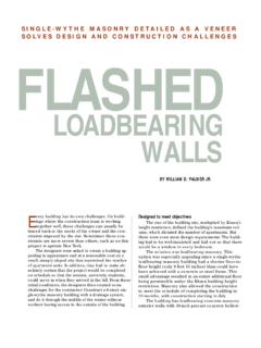
2 Bond Beams can provide a location of solid mass within a MASONRY wall to support distributed and point loads as part of either the gravity or lateral resisting systems. With correct detailing, they can also be used for crack control within a MASONRY wall. Figure 1 shows a plan section view of a bond beam and Figure 2 illustrates elevation views of stepped and sloped bond CMU blocks do not readily incorporate horizontal rebar, thus special MASONRY units are typically used at the bond beam locations. Bond beam units are prefabricated blocks, as MASONRY INSIGHTS(2a) Stepped (2b) SlopedFigure 2: Bond BeamsTMS 402-13 Section Commentary Figure 1: Bond Beam Plan Section ncma TEK 10-2c FORSE Consulting, LLC2018shown at the top of Figure 3, with either part of the webs removed during fabrication or saw-cut slots creating knock-out panels which are removed with a hammer by the mason in the field. Both unit types have vertical cores aligning with standard stretcher blocks that allow for installation of vertical reinforcement as well.
3 Lintel units, as shown at the bottom of Figure 3, can also be used for constructing bond Beams . However, since lintel units do not accommodate vertical reinforcement without field cutting, they are better suited for walls that are considered to be unreinforced. Requirements for bond beam horizontal reinforcement bar size, spacing, and cover dimensions are the same as for vertical rebar which are found in TMS 402-13 section , a bond beam is located at the top course of each MASONRY wall or parapet as well as at each roof and floor diaphragm. In typical conditions, it is optimal for bond beam reinforcement to terminate at each side of a control joint, to achieve full movement separation between walls. However, there may instances where continuity through a control joint is required for bond beam reinforcement, such as for bond Beams serving as collector elements and/or diaphragm chords. When required, bond beam reinforcement can be continuous through a joint using a smooth dowel with one end debonded crossing the Beams are also one option to connect intersecting MASONRY walls if the transfer of loads between them is necessary per the structural design (see Figure 4).
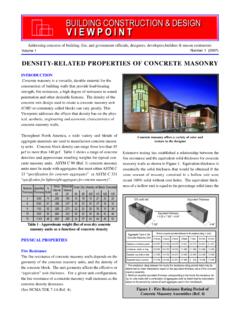
4 In this case, bond Beams must be located within the wall at a maximum spacing of 48 on center, have the reinforcement be fully developed each side of the intersection, and have at least half of the MASONRY units interlock at the interface. One example of a situation where this connection may be required is when a shear wall does not have adequate capacity, thus the intersecting wall is tied to the end of the shear wall to serve as a flange for additional gravity loading, MASONRY walls have capacity to support large concentrated loads from steel bar joists, Beams , or other structural elements. Depending on the MASONRY wall detailing, the calculated wall capacity will vary. The MASONRY bond pattern and bearing plate size determine the effective bearing length of the wall and thus how much wall area can be included in the capacity calculation (see Figure 5). For stack bond, the load dispersement cannot go further than the first CMU head joint that the sloped line meets.
5 Thus if a point load is bearing directly on 2 Figure 3: Bond Beam UnitsNCMA TEK 3-2 AFigure 4: Bond Beam at Wall IntersectionTMS 402-13 Section Commentary FORSE Consulting, LLC2018the MASONRY , the effective length will likely only be the length of one block unless the bearing plate straddles a joint. As demonstrated in figure 5, inserting a bond beam into the wall at the location of the point load can significantly increase the effective bearing length for stack bond construction. Horizontal Reinforcement Bond Beams offer an alternative means of crack control in MASONRY walls where control joints are not desired. In design cases where a MASONRY wall may have large openings or multiple openings close together, control joints may lead to inadequate structural capacity. Other times there may be architectural design elements which require control joints to be spaced further apart than the standard joint spacing recommendations. A rational engineering approach can be implemented for the use of horizontal reinforcement to control cracks, in lieu of utilizing control joints in specific areas of a structure.
6 Standard horizontal reinforcement bars at a maximum of 48 on center have shown effective crack control. Since a typical MASONRY stretcher block does not easily accommodate horizontal rebar, installing bond Beams in the MASONRY wall is a good solution. To determine the spacing of the bond Beams , calculations are required based on the thermal expansion coefficient of MASONRY as well as the yield strain of the rebar to limit the crack widths, while keeping the steel in the elastic range. Fortunately, the National Concrete MASONRY Association ( ncma ) has already performed the calculations for standard conditions and have summarized the information in Figure 6 as a table showing the maximum horizontal reinforcement spacing for several common rebar more condition where bond Beams are effective is in the shear walls of buildings located in areas of high seismicity. Horizontal reinforcement increases the in-plane ductility of the MASONRY assembly.
7 Section of TMS 402-13 provides minimum horizontal reinforcement requirements based on the seismic classification of the building site, the magnitude of the lateral loads, and the detailing designation of the shear wall. For shear walls with lower seismic detailing, the horizontal reinforcement minimum can be satisfied with either joint reinforcement or bond beam reinforcement. Higher seismic detailing is more stringent with bond beam reinforcement as the only option. 3 Bond BeamBearing PlateLoad dispersion terminates at head joint in stack bondBond BeamLoadBearing PlateCheck bearing on hollow wallLoad is dispersed at a 2:1 slopeRunning bondLoadStack bondBond BeamBearing PlateLoad dispersion terminates at head joint in stack bondBond BeamLoadBearing PlateCheck bearing on hollow wallLoad is dispersed at a 2:1 slopeRunning bondLoadStack bondBond BeamBearing PlateLoad dispersion terminates at head joint in stack bondBond BeamLoadBearing PlateCheck bearing on hollow wallLoad is dispersed at a 2:1 slopeRunning bondLoadStack bondBond BeamBearing PlateLoad dispersion terminates at head joint in stack bondBond BeamLoadBearing PlateCheck bearing on hollow wallLoad is dispersed at a 2:1 slopeRunning bondLoadStack bondFigure 5: Concentrated Load Dispersion TMS 402-13 Section Commentary Figure 6: Reinforcement Only Crack Control Maximum Rebar SpacingNCMA TEK 10-3