Transcription of MASTER
1 Installation and Operation Manual MP-NS-20T COMBINATION UNIT with the 255/762 Logix Control Valve MASTERW ater Conditioning March 2006 Table of Contents Page No. Topic Description 1 Model # and Packaging Packaging Information Component Packaging Description Packaging Description MP Logix Control Valve Valve Description 2 Combination Unit System Positioning Combination Unit Tank Loading Filling with Media 3 Logix 255/762 Control Valve Attaching Valve to Tank Figure 1 & Figure 2 4 Service & Drain Piping, General Installation Layout Drain Piping Figure 3 5 System Schematic Piping Layout 6 Electrical Supply Electrical Requirements Brine Tank / Brine Tubing Brine tank w/shut off 7 Logix 255/762 Control Valve Electrical Connection Instructions on Logix 762 Electrical Connection 8 Filling Combination Unit with Water Details for Filling Combination Unit Tank with Water 9 Filling Combination Unit With Water Continued Details for Filling Combination Unit Tank with Water Continued Logix 762 Control Valve Timer Settings Setting the Timer 10 Logix 762 Control Valve Timer Settings Continued Setting the Timer Continued Final Check Final Installation Check 11 Troubleshooting Symptom / Cause
2 / Solution 12 Troubleshooting Symptom / Cause / Solution 13 Troubleshooting Symptom / Cause / Solution 14 ERR Troubleshooting Error Troubleshooting 15 255/762 Valve Body Schematic Parts View 16 Valve Body Parts List Part Numbers List 17 Valve Parts List Part Numbers List 18 Warranty Warranty 1 Installation and Operating Instructions for 255/762 Logix with 434 Shutoff Top Mount Combination Unit Model #: ____ MP-NS-20T Acid Neutralizer and Softener Shipping Carton Description / unit: # of cartons Contents Description 1 Mineral tank Distributor pipe installed 1 Brine tank *NOTE: 255/762 Logix valved is shipped in brine tank. 1 255/762 Logix control valve 255/762 timer and backwash flow control and bypass with 3/4 copper or pvc connection NS-Mix for NS CF Boxes *Note:The MP-NS-20T units have Vortech and do not require gravel.
3 System Description: The combination unit has a Logix top mounted automatic control valve with an impulse meter to initiate regeneration. The Logix Valve is constructed of non-corrosive Noryl material and is rated at a maximum working water pressure of 100 psi. It uses a 762 microprocessor based timer in conjunction with an internal impulse meter to actuate regeneration in the following ways: a. Microprocessor based water meter to initiate regeneration b. Manual regeneration button to start an emergency regeneration c. Calendar day override NOTE: THIS COMBO IS NOT INTENDED TO BE USED FOR TREATING WATER THAT IS MICROBIOLOGICALLY UNSAFE OR OF UNKNOWN QUALITY WITHOUT ADEQUATE DISINFECTION WHETHER BEFORE OR AFTER THE SYSTEM 2 Combination Unit Positioning: 1.
4 Place combination unit in desired position, far enough from walls and other obstructions to allow for servicing the unit. 2. Place the combination unit within reasonable access to a grounded 115V/60 HZ circuit and a legal drain line connection. Combination Unit Tank Loading: 1. Remove yellow caplug from top of tank. DO NOT CUT white riser tube. Tube was prefitted at the factory. 2. Center the distributor and make sure it is resting on the bottom of the tank. The top of the distributor pipe will extend above the top of the tank (this was prefitted at the factory). 3. Cover the top opening of the distributor pipe before filling the tank with media. Model Filter Media MP-NS-20T 1/2-cubic foot NS-Mix 4.
5 Pour all filter media provided with the unit into the top of the tank. See page one for your specific model number of unit to determine the amount of media to load into the mineral tank. 5. Remove the material used to cover the top opening of the distributor pipe. 3 Logix Control Valve: 1. When facing the front of the Logix timer, the inlet connection (Figure 1) is located on the left and the outlet connection is on the right. The control valve's inlet and outlet connections are either 1 copper or pvc equipped with gasket and nut. Figure 1 Install the 256 bypass valve (See Figure 2) with inlet and outlet handles facing upward. Place gasket into nut and secure 1 copper or pvc tail piece with a nut.
6 Repeat the procedure for the outlet connection. DO NOT OVERTIGHTEN THE NUT. Figure 2 2. The control valve's drain connection is 1/2" npt and is located on the back of the control valve. 3. Turn the control valve upside down and ensure that the control valve distributor o'rings are in place. Use silicone lubricant on the o'rings. 4. Place the control valve onto the distributor pipe. 5. Thread the control valve hand tight to 20 foot pounds! DO NOT OVERTIGHTEN! **DO NOT USE PETROLEUM!** **USE ONLY SILICONE ** 4 Service and Drain Piping: 1. Pipe combination unit into the service lines .The inlet and outlet connections of the control valve are 3/4 copper or pvc and are located on the back of the valve body.
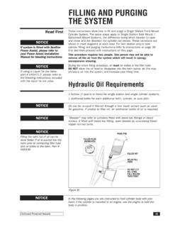
7 As you face the timer the inlet is on the left and and the outlet is on the right. Always follow local plumbing codes when installing our water treatment equipment. 2. If sweat fittings are used, be sure soldering is done in such a manner as not to allow heat to reach the control valve or bypass. (If Schedule 80 PVC is used make sure to follow the proper primer and solvent instructions.) 3. The drain line connection is located on the back of the valve as you face the timer. It is recommended you install a union on the drain line for servicing. The drain line must be of adequate size to allow for full regeneration flow. Figure 3 The control valve drain connection is 1/2" npt.
8 Never decrease the drain piping size to below Maximum drain line length is 30 feet. Maximum drain line height is 6 feet above the control valve. The drain line must be piped to an open airgap (See Figure 3) Always follow local plumbing codes. UNDER NO CIRCUMSTANCES SHOULD THERE BE A DIRECT CONNECTION WITH SANITARY SEWAGE FACILITIES. 5 Well TankUntreatedwater from wellNOTE: All MASTER Water Conditioners must beinstalled after the well tank or water meter if itspublic water WaterConditionerBrine tankAir Gap DrainOverflowfitting tofloor draingravityTreated waterUntreated to outside224 Shoemaker , PA 19464 Typical Piping Layout 6 Electrical Requirements: Always follow all local electrical codes when installing our water treatment equipment.
9 1. Provide an 115v/60Hz properly grounded dedicated electrical outlet. (It s very important that the polarity be correct) Avoid using outlets that are switch controlled. 2. Maximum amperage required is 5 amps. 3. Make sure the electrical service provides power 24 hours per day. We recommend installing a surge protector to protect unit from power surges, which are not covered by warranty. Brine Tank: 1. The brine tank should be located directly beside the Combination Unit mineral tank. 2. Connect the 3/8" poly tubing to the 3/8 white elbow compression fitting located on the right side of the Logix control valve. See Figure Below.
10 If the unit has a shut off; t he float height was preset at the factory. 7 Logix Control Valve Electrical Connection: Note: Do not touch the wiring harness between the Logix timer and the motor, it s positioning is critical and therefore already installed at the factory. 1. Remove plastic control valve cover by spreading sides while lifting. 2. Plug transformer into back of timer following existing wires. 3. Plug transformer into a properly grounded 120V/60 HZ electrical outlet. 4. The screen will now change between the Gallons Remaining to Regeneration and the current Gallons per Minute (gpm) flow rate.