Transcription of MASTERING MIXING FUNDAMENTALS
1 MASTERING . MIXING . FUNDAMENTALS . A technical guide from the experts in the industry 2019. Technical Guide Mixer Tech Guide Website: | Email: Hayward Gordon has supplied impeller type fluid agitation equipment to the process industries for over 40 years acquiring considerable expertise in this field. Combining both experience and theory, this section covers the basics of fluid mechanics of MIXING , the main criteria for mixer sizing and application limitations of fluid mixers. Fluid MIXING Technically, matter in the liquid or gas state is considered a fluid. For the purposes of fluid mixers , a fluid is defined as a liquid (or mixture of liquids), which may contain modest amounts of solid particles or gas bubbles. The presence of solids or gas must not alter the basic capacity of the fluid to flow . and be pumped about in the MIXING vessel by a MIXING impeller. A liquid must always be present, either thin with a water-like viscosity or thick with a relatively high viscosity.
2 The thickest liquid that can be handled with a fluid mixer will typically have a viscosity less than 500,000 centipoise. The simplest and most common fluid MIXING application is simply to add liquid A to liquid B , where the liquids are soluble in one another, and blend them to uniformity. Application requirements can include the time available to mix the liquids and the degree of uniformity to which they must be mixed. The second most common MIXING application is the suspension of solid particles in a liquid. This can be for the purpose of dissolving the solids, leaching out valuable components in the solids, allowing the solids to participate in a chemical reaction with the liquid, or simply to keep the solids in suspension. The typical maximum concentration of solids which can be effectively mixed with a fluid mixer is 70-75% solids by weight. Other functions of fluid mixers include dispersion of a gas into a liquid, dispersion of insoluble liquids into one another and heat transfer applications.
3 MIXING impellers are designed to pump fluid through the impeller and produce turbulence - both of these effects are essential to MIXING . They produce fluid velocity and fluid shear respectively. Fluid velocity produces movement throughout the MIXING vessel, intermixing material in one part of the tank with another, prevents solids from settling out and produces flow over heating or cooling coils when necessary. Fluid shear, in the form of turbulent eddies, is essential to micro- MIXING within the large velocity streams breaking up gas bubbles or immiscible liquids into small droplets. All MIXING impellers produce both fluid velocity and fluid shear, but different types of impellers produce different degrees of flow and turbulence, either of which may be important, depending on the application. Fluid mechanics of MIXING All impellers produce two results within the MIXING chamber: circulation of fluid and fluid shear. The power P consumed by an impeller is related to the volumetric circulation rate Q (pumping capacity).
4 And the velocity Head Delta H from the impeller by: P = QrDH. The pumping capacity of an impeller is defined as the volumetric flow rate normal to the impeller discharge area. The pumping capacity of an impeller is proportional to its diameter and speed: Q a ND3. The head difference between the suction and discharge surfaces of an impeller blade results in fluid shear, which is also proportional to impeller diameter and speed: DH a N 2 D 2. In general form: P a r ( ND 3 )( N 2 D 2 ). P = kr ( ND 3 )( N 2 D 2 ). P = kr ( N 3 D5 ). This development illustrates one of the basic principles of fluid MIXING : for a constant horsepower, as impeller size increases, more power is expended on flow and less on shear. A large impeller running at a slow speed produces high pumping and low shear. Conversely, a small impeller running at high speed produces relatively low pumping capacity and high fluid shear. Some process, such as flocculation, are shear sensitive and require high flow, low shear MIXING .
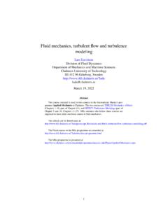
5 Other processes, such as gas dispersion, are at the other end of the scale and require high shear MIXING . The selection of a mixer for a particular application depends on numerous process factors, some of which are: Type of application (high flow or high shear requirements). Viscosity, % solids, amount of gas addition Tank Geometry Retention time and/or blend time Viscosity Effect The previous equations show the effect that a fluid's density has on the power draw of a MIXING impeller. The next most common factor affecting power draw is viscosity. The graph below shows the relationship between viscosity and a MIXING impellers power response - power draw increases with increasing viscosity. Every impeller has a Power Number vs. Reynolds Number curve similar to the one show below. The straight line portion at the left hand side is the laminar range which develops into the transition range and finally reaches a plateaus at a constant power number in the fully turbulent range.
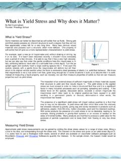
6 Power numbers of various impellers are normally compared in the fully turbulent range which typically starts at NRe=103 to 104. Power Number - Reynolds Number Correlation 100. Power Number, NP. 10. 1. 10 0 10 1 10 2 10 3 10 4 10 5. Reynolds Number, NRe The viscosity of a fluid can have a significant impact on the overall mixer sizing for a particular application. The graph below shows the relative increase of theoretical tank turnovers for viscosities from 10 to 10,000 cps. Basic Essentials of Mixer Sizing The main sizing criteria for most applications are: Torque Invested into the Mix Impeller Style Impeller Diameter to Tank Diameter (D/T) Ratio Mixer Horsepower Pumping Capacity Impeller Tip Speed Superficial Velocity Torque/Equivalent Volume Torque In order for power (the rate at which work is done) to be meaningful there must be a standard of comparison. The most common unit to measure linear force is horsepower which is defined as the energy to move 100 pounds 330 feet in 1 minute or 33,000 Ft-Lbs/Min.
7 Mechanical transmission products, such as gearboxes, are evaluated on the basis of torque or rotational energy. Rotational power is defined as force times angular velocity. The angular velocity of a MIXING impeller is normally measured in revolutions per minute (RPM). The amount of torque applied to a fluid mix is one of the most important factors in determining MIXING results. Using the most common units, torque is defined as: HP 63025. Torque = [inch - lbs]. RPM. As can be seen from the equation, at a given horsepower, a relatively high mixer speed and small impeller diameter will result in lower torque (and therefore a lower MIXING level) than a larger impeller turning at a lower speed. Impeller Styles MIXING impellers fall into one of two categories: Radial Flow or Axial Flow. Radial flow impellers have multiple flat blades mounted parallel to the axis of the MIXING shaft. The blades can be attached to a disc forming a closed impeller or on a simple hub making an open style impeller.
8 Typical uses are gas/liquid dispersion, liquid/liquid dispersion, flash MIXING and low level MIXING applications. Axial flow impellers have blades which make an angle of less than 900 with the MIXING shaft axis. These impellers are further classified as A) constant angle of attack or B) variable angle of attack. The first group includes pitched blade turbines and the second group includes propellers and hydrofoils. Typical applications include simple blending, solids suspension and flocculation. Radial Flow Turbines Power Number, NP = to Pumping Number, NQ = to Applications: High Shear Gas\Liquid Dispersion Liquid Liquid Dispersion Low Level MIXING Pitched Blade Turbines (Constant Angle of Attack). NP = to NQ = to Applications/Uses: Moderate Shear & Moderate Flow Moderate Viscosity MIXING High Intensity MIXING for Flow Dependent Applications Inexpensive Axial Flow Impeller Low and Mid Solidity Hydrofoils (Variable Angle of Attack). NP = to NQ = to Applications/Uses: High Flow & Low Shear Low to Moderate Viscosities Limited Gas Dispersion for High Solidity Design Positioned Relatively High off Tank Bottom Impeller Diameter/Tank Diameter (D/T) Ratio The impeller diameter to tank diameter ratio typically falls in the range of to The low end of the range is used for waterlike viscosities and increases as the mixture viscosity increases.
9 Refer to page for optimum D/T ratios for various viscosities. Horsepower Although horsepower on its own is not enough to define the size of a mixer for most (flow sensitive). applications to ensure a certain process result, it is still an important consideration. Some applications, such as gas/liquid or liquid/liquid dispersions are quite sensitive to the HP invested. The equation to determine the power draw of one impeller is: N P D 5 N 3 SG. BHP =. 10 7. Where: NP = Impeller Power Number [Dimensionless]. D = Impeller Diameter [Feet]. N = Impeller Speed [RPM]. SG = Fluid Specific Gravity And: NP is adjusted for viscosity, proximity, blade width and number of blades. Primary Pumping Capacity (Q). The equation below calculates the Primary pumping capacity of one impeller and does NOT include entrained flow. Total flow (Primary + Entrained) is often considered to be to 3 times greater. Q = NQ N D3 [USGPM ]. Where: NQ = Pumping Number [Dimensionless]. D = Impeller Diameter [Feet].
10 N = Impeller Speed [RPM]. Tip Speed (TS). Impeller tip speeds are normally in the range of 400 to 1500 FPM. Tip speed is a more important criteria for some applications than others, ie. flocculation or dispersion. TS = D N [FPM]. Where: D = Impeller Diameter [Feet]. N = Impeller Speed [RPM]. Superficial Velocity (SV). Normally used for solid suspension applications and compared to the settling rate of the solid in question. Superficial Velocity is calculated using the following equation: Q. SV = [ FPM ]. A. Where: Q = Pumping Capacity [USGPM]. A = Tank Cross Sectional Area [Ft2]. Torque per Equivalent Volume (TQ/Eq V). This is an extremely useful ratio which is the basis for all Hayward Gordon mixer sizing and describes the level of MIXING for any application. BHP 63025 . TQ . = N [in - lbs / ]. Eq V SG V .. Where: V = Working Volume of Tank [USG]. SG = Fluid Specific Gravity Equation Summary Impeller Diameter (ft) Torque per Equivalent Volume (in-lbs/Eq. Vol). BHP 63025.