Transcription of MAX3372E–MAX3379E/ MAX3390E–MAX3393E ±15kV ESD …
1 General DescriptionThe MAX3372E MAX3379E and MAX3390E MAX3393E 15kv ESD- protected level translators provide the level shifting necessary to allow data transfer in a multivolt-age system. Externally applied voltages, VCC and VL, set the logic levels on either side of the device. A low-voltage logic signal present on the VL side of the device appears as a high-voltage logic signal on the VCC side of the device, and vice-versa. The MAX3374E/MAX3375E/MAX3376E/MAX3379E and MAX3390E MAX3393E uni-directional level translators level shift data in one direc-tion (VL VCC or VCC VL) on any single data line. The MAX3372E/MAX3373E and MAX3377E/MAX3378E bidirectional level translators utilize a transmission-gate-based design (Figure 2) to allow data translation in either direction (VL VCC) on any single data line. The MAX3372E MAX3379E and MAX3390E MAX3393E accept VL from + to + and VCC from + to + , making them ideal for data transfer between low-voltage ASICs/PLDs and higher voltage devices in the MAX3372E MAX3379E, MAX3390E MAX3393E family feature a three-state output mode that reduces supply current to less than 1 A, thermal shortcircuit protection, and 15kv ESD protection on the VCC side for greater protection in applications that route signals externally.
2 The MAX3372E/MAX3377E operate at a guaranteed data rate of 230kbps. Slew-rate limit-ing reduces EMI emissions in all 230kbps devices. The MAX3373E MAX3376E/MAX3378E/MAX3379E and MAX3390E MAX3393E operate at a guaranteed data rate of 8 Mbps over the entire specified operating voltage range. Within specific voltage domains, higher data rates are possible. (See the Timing Characteristics table.)The MAX3372E MAX3376E are dual level shifters avail-able in 3 x 3 UCSP , 8-pin TDFN, and 8-pin SOT23-8 packages. The MAX3377E/MAX3378E/MAX3379E and MAX3390E MAX3393E are quad level shifters available in 3 x 4 UCSP, 14-pin TDFN, and 14-pin TSSOP SPI, MICROWIRE, and I2C Level Translation Low-Voltage ASIC Level Translation Smart Card Readers Cell-Phone Cradles Portable POS Systems Portable Communication Devices Low-Cost Serial Interfaces Cell Phones GPS Telecommunications EquipmentFeatures Logic-Level Translators Simplify Design by Enabling Data Transfer Between Lower and Higher Voltage Systems Operation Down to + on VL Guaranteed Data Rate Options 230kbps 8 Mbps (+ VL VCC + ) 10 Mbps (+ VL VCC + ) 16 Mbps (+ VL VCC + and + VL VCC + ) Bidirectional Level Translation (MAX3372E/MAX3373E and MAX3377E/MAX3378E) Low Power Consumption Reduces Thermal Dissipation Quiescent Current (130 A typ)
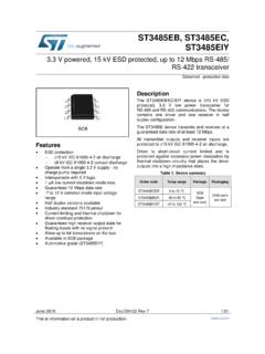
3 1 A Supply Current in Three-State Output Mode Slew-Rate Limiting Lowers EMI Protection Features Increase System Reliability 15kv ESD Protection on I/O VCC Lines Thermal Short-Circuit Protection19-2328; Rev 7; 2/20 UCSP is a trademark of Maxim Integrated Products, Information continued at end of data sheet. Selector Guide appears at end of data VCC1I/0 VL2I/O VL1 MAX3377E/MAX3378 EVLI/0 VCC3 GNDI/O VL4I/O VL3 TDFN-14(3mm x 3mm)THREE-STATEI/0 VCC4 TOP VIEW+Pin Configurations continued at end of data MAX3379E/MAX3390E MAX3393E 15kv ESD- protected , 1 A, 16 Mbps, Dual/QuadLow-Voltage Level Translators in UCSPPin ConfigurationsClick here for production status of specific part numbers.(All voltages referenced to GND.)VCC .. to +6VI/O VCC_ .. to (VCC + )I/O VL_ .. to (VL + )THREE-STATE .. to (VL + )Short-Circuit Duration I/O VL, I/O VCC to GND ..ContinuousShort-Circuit Duration I/O VL or I/O VCC to GND Driven from 40mA Source (except MAX3372E and MAX3377E).
4 ContinuousContinuous Power Dissipation (TA = +70 C) 8-Pin SOT23 (derate C above +70 C) .. 8-Pin TDFN (derate C above +70 C) ..1482mW 3 x 3 UCSP (derate C above +70 C) ..379mW 3 x 4 UCSP (derate C above +70 C) ..520mW 14-Pin TSSOP (derate C above +70 C) ..727mW 14-Pin TDFN (derate C above +70 C) ..1482mWOperating Temperature Range ..-40 C to +85 CStorage Temperature Range ..-65 C to +150 CLead Temperature (soldering, 10s) ..+300 CSoldering Temperature (reflow) ..+260 C(VCC = + to + , VL = + to (VCC + ), GND = 0, I/O VL_ and I/O VCC_ unconnected, TA = TMIN to TMAX, unless other-wise noted. Typical values are at VCC = + , VL = + , TA = +25 C.) (Notes 1, 2)PARAMETER SYMBOLCONDITIONSMINTYPMAXUNITSPOWER SUPPLIESVL Supply Supply Current from VCCIQVCC130300 ASupply Current from VLIQVL16100 AVCC Three-State Output Mode Supply CurrentITHREE-STATE-VCCTA = +25 C, THREE-STATE = AVL Three-State Output Mode Supply CurrentITHREE-STATE-VLTA = +25 C, THREE-STATE = AThree-State Output Mode Leakage CurrentI/O VL_ and I/O VCC_ITHREE-STATE-LKGTA = +25 C, THREE-STATE = ATHREE-STATE Pin Input LeakageTA = +25 AESD PROTECTIONI/O VCC (Note 3) IEC 1000-4-2 Air-Gap Discharge 8kVIEC 1000-4-2 Contact Discharge 8 Human Body Model 15 LOGIC-LEVEL THRESHOLDS (MAX3372E/MAX3377E)I/O VL_ Input-Voltage High VIHLVL - VL_ Input-Voltage Low MAX3379E/MAX3390E MAX3393E 15kv ESD- protected , 1 A, 16 Mbps, Dual/QuadLow-Voltage Level Translators in Integrated 2 Absolute Maximum RatingsStresses beyond those listed under Absolute Maximum Ratings may cause permanent damage to the device.
5 These are stress ratings only, and functional operation of the device at these or any other conditions beyond those indicated in the operational sections of the specifications is not implied. Exposure to absolute maximum rating conditions for extended periods may affect device Characteristics(VCC = + to + , VL = + to (VCC + ), GND = 0, I/O VL_ and I/O VCC_ unconnected, TA = TMIN to TMAX, unless other-wise noted. Typical values are at VCC = + , VL = + , TA = +25 C.) (Notes 1, 2)PARAMETER SYMBOLCONDITIONSMINTYPMAXUNITSI/O VCC_ Input-Voltage High VIHCVCC - VCC_ Input-Voltage Low VL_ Output-Voltage High VOHLI/O VL_ source current = 20 A,I/O VCC_ > VCC - x VLVI/O VL_ Output-Voltage Low VOLLI/O VL_ sink current = 20 A,I/O VCC_ < VCC_ Output-Voltage HighVOHCI/O VCC_ source current = 20 A,I/O VL _ > VL - x VCCVI/O VCC_ Output-Voltage LowVOLCI/O VCC_ sink current = 20 A,I/O VL_ < Input-Voltage High VIL-THREE-STATEVL - Input-Voltage Low THRESHOLDS (MAX3373E MAX3376E/MAX3378E/MAX3379E and MAX3390E MAX3393E)
6 I/O VL_ Input-Voltage High VIHLVL - VL_ Input-Voltage Low VCC_ Input-Voltage High VIHCVCC - VCC_ Input-Voltage Low VL_ Output-Voltage High VOHLI/O VL_ source current = 20 A,I/O VCC_ VCC - x VLVI/O VL_ Output-Voltage LowVOLLI/O VL_ sink current = 1mA,I/O VCC_ VCC_ Output-Voltage HighVOHCI/O VCC_ source current = 20 A,I/O VL_ VL - x VCCVI/O VCC_ Output-Voltage LowVOLCI/O VCC_ sink current = 1mA,I/O VL_ Input-Voltage High VIH-THREE-STATEVL - Input-Voltage Low MAX3379E/MAX3390E MAX3393E 15kv ESD- protected , 1 A, 16 Mbps, Dual/QuadLow-Voltage Level Translators in Integrated 3 Electrical Characteristics (continued)(VCC = + to + , VL = + to (VCC + ), GND = 0, RLOAD = 1M , I/O test signal of Figure 1, TA = TMIN to TMAX, unless otherwise noted. Typical values are at VCC = + , VL = + , TA = +25 C, unless otherwise noted.) (Notes 1, 2)PARAMETERSYMBOLCONDITIONSMINTYPMAXUNIT SMAX3372E/MAX3377E (CLOAD = 50pF)I/O VCC_ Rise Time (Note 4)tRVCC1100nsI/O VCC_ Fall Time (Note 5)tFVCC1000nsI/O VL _ Rise Time (Note 4)tRVL600nsI/O VL _ Fall Time (Note 5)tFVL1100nsPropagation Delay I/OVL-VCCD riving I/O VL sI/OVCC-VLDriving I/O VCC_ SkewtSKEWEach translator equally loaded 500nsMaximum Data RateCL = 25pF 230kbpsMAX3373E MAX3376E/MAX3378E/MAX3379E and MAX3390E MAX3393E (CLOAD = 15pF, Driver Output Impedance 50 )+ VL VCC + VCC_ Rise Time (Note 4)tRVCC725nsOpen-drain driving170400I/O VCC_ Fall Time (Note 5)tFVCC637nsOpen-drain driving2050I/O VL _ Rise Time (Note 4)tRVL830nsOpen-drain driving180400I/O VL _ Fall Time (Note 5)
7 TLFV330nsOpen-drain driving3060 Propagation DelayI/OVL-VCCD riving I/O VL _ 530nsOpen-drain driving2101000I/OVCC-VLDriving I/O VCC_ 430 Open-drain driving1901000 Channel-to-Channel SkewtSKEWEach translator equally loaded20nsOpen-drain driving50 Maximum Data Rate8 MbpsOpen-drain driving500kbpsMAX3372E MAX3379E/MAX3390E MAX3393E 15kv ESD- protected , 1 A, 16 Mbps, Dual/QuadLow-Voltage Level Translators in Integrated 4 Timing Characteristics(VCC = + to + , VL = + to (VCC + ), GND = 0, RLOAD = 1M , I/O test signal of Figure 1, TA = TMIN to TMAX, unless otherwise noted. Typical values are at VCC = + , VL = + , TA = +25 C, unless otherwise noted.) (Notes 1, 2)Note 1: All units are 100% production tested at TA = +25 C. Limits over the operating temperature range are guaranteed by design and not production 2: For normal operation, ensure VL < (VCC + ). During power-up, VL > (VCC + ) will not damage the 3: To ensure maximum ESD protection, place a 1 F capacitor between VCC and GND.
8 See Applications 4: 10% to 90%Note 5: 90% to 10%PARAMETERSYMBOLCONDITIONSMINTYPMAXUNI TS+ VL VCC + VCC_ Rise Time (Note 4)tRVCC25nsI/O VCC_ Fall Time (Note 5)tFVCC30nsI/O VL _ Rise Time (Note 4)tRVL30nsI/O VL _ Fall Time (Note 5)tFVL30nsPropagation DelayI/OVL-VCCD riving I/O VL _ 20nsI/OVCC-VLDriving I/O VCC_ 20 Channel-to-Channel SkewtSKEWEach translator equally loaded10nsMaximum Data Rate10 Mbps+ VL VCC + VCC_ Rise Time (Note 4)tRVCC15nsI/O VCC_ Fall Time (Note 5)tFVCC15nsI/O VL _ Rise Time (Note 4)tRVL15nsI/O VL _ Fall Time (Note 5)tFVL15nsPropagation DelayI/OVL-VCCD riving I/O VL _ 15nsI/OVCC-VLDriving I/O VCC_ 15 Channel-to-Channel SkewtSKEWEach translator equally loaded10nsMaximum Data Rate16 Mbps+ VL VCC + VCC_ Rise Time (Note 4)tRVCC15nsI/O VCC_ Fall Time (Note 5)tFVCC15nsI/O VL _ Rise Time (Note 4)tRVL15nsI/O VL _ Fall Time (Note 5)tFVL15nsPropagation DelayI/OVL-VCCD riving I/O VL _ 15nsI/OVCC-VLDriving I/O VCC_ 15 Channel-to-Channel SkewtSKEWEach translator equally loaded10nsMaximum Data Rate16 MbpsMAX3372E MAX3379E/MAX3390E MAX3393E 15kv ESD- protected , 1 A, 16 Mbps, Dual/QuadLow-Voltage Level Translators in Integrated 5 Timing Characteristics (continued)(RLOAD = 1M , TA = +25 C, unless otherwise noted.)
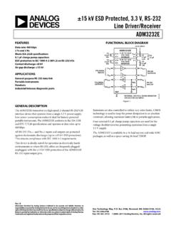
9 All 230kbps TOCs apply to MAX3372E/MAX3377E only. All 8 Mbps and 500kbps TOCs apply to MAX3373E MAX3376E/MAX3378E/MAX3379E and MAX3390E MAX3393E only.)VCC SUPPLY CURRENT vs. SUPPLY VOLTAGE(DRIVING I/O VL, VCC = + , VL = + )MAX3372E toc02 VCC (V)SUPPLY CURRENT ( A) , CLOAD = 15pF230kbps, CLOAD = 50pF500kbps, OPEN-DRAIN, CLOAD = 15pFVL SUPPLY CURRENT vs. TEMPERATURE(DRIVING I/O VCC, VCC = + , VL = + )MAX3372E toc03 TEMPERATURE ( C)SUPPLY CURRENT ( A)6035-1510501001502002503003504000-4085 8 Mbps, CLOAD = 15pF230kbps, CLOAD = 50pF500kbps, OPEN-DRAIN, CLOAD = 15pFVCC SUPPLY CURRENT vs. TEMPERATURE(DRIVING I/O VCC, VCC = + , VL = + )MAX3372E toc04 TEMPERATURE ( C)SUPPLY CURRENT ( A)6035-151020040060080010001200140016000 -40858 Mbps, CLOAD = 15pF230kbps, CLOAD = 50pF500kbps, OPEN-DRAIN, CLOAD = 15pFVL SUPPLY CURRENT vs. CAPACITIVE LOAD(DRIVING I/O VL, VCC = + , VL = + )MAX3372E toc05 CAPACITIVE LOAD (pF)SUPPLY CURRENT ( A)8570554025501001502002503003500101008 Mbps230kbps500kbps, OPEN-DRAINVCC SUPPLY CURRENT vs.
10 CAPACITIVE LOAD(DRIVING I/O VL, VCC = + , VL = + )MAX3372E toc06 CAPACITIVE LOAD (pF)SUPPLY CURRENT ( A)857055402550010001500200025000101008 Mbps230kbps500kbps, OPEN-DRAINRISE/FALL TIME vs. CAPACITIVE LOAD(DRIVING I/O VL, VCC = + , VL = + )MAX3372E toc07 CAPACITIVE LOAD (pF)RISE/FALL TIME (ns)908070605040305001000150020002500020 100 DATA RATE = 230kbpstHLtLHVL SUPPLY CURRENT vs. SUPPLY VOLTAGE(DRIVING I/O VL, VCC = + , VL = + )MAX3372E toc01 VCC (V)SUPPLY CURRENT ( A) , CLOAD = 15pF230kbps, CLOAD = 50pF500kbps, OPEN-DRAIN, CLOAD = 15pFRISE/FALL TIME vs. CAPACITIVE LOAD(DRIVING I/O VL, VCC = + , VL = + )MAX3372E toc08 CAPACITIVE LOAD (pF)RISE/FALL TIME (ns)454030352025152468101214161801050 DATA RATE = 8 MbpstHLtLHRISE/FALL TIME vs. CAPACITIVE LOAD(DRIVING I/O VL, VCC = + , VL = + )MAX3372E toc09 CAPACITIVE LOAD (pF)RISE/FALL TIME (ns)454035302520155010015020025001050tLH tHLDATA RATE = 500kbps,OPEN-DRAINMAX3372E MAX3379E/MAX3390E MAX3393E 15kv ESD- protected , 1 A, 16 Mbps, Dual/QuadLow-Voltage Level Translators in UCSPM axim Integrated Operating Characteristics(RLOAD = 1M , TA = +25 C, unless otherwise noted.)