Transcription of MAX4238/MAX4239 - Ultra-Low Offset/Drift, Low-Noise ...
1 Pin Configurations appear at end of data Information appears at end of data DescriptionThe MAX4238/MAX4239 are Low-Noise , low-drift, ultra-high precision amplifiers that offer near-zero DC offset and drift through the use of patented autocorrelating zeroing techniques. This method constantly measures and compensates the input offset, eliminating drift over time and temperature and the effect of 1/f noise. Both devices feature rail-to-rail outputs, operate from a single to supply, and consume only 600 A. An active-low shutdown mode decreases supply current to MAX4238 is unity-gain stable with a gain-bandwidth product of 1 MHz, while the decompensated MAX4239 is stable with AV 10V/V and a GBWP of The MAX4238/MAX4239 are available in 8-pin narrow SO, 6-pin TDFN and SOT23 Thermocouples Strain Gauges Electronic Scales Medical instrumentation instrumentation Amplifiers AutomotiveBenefits and Features DC Performance Ideal for High-Precision Sensor Interface Ultra-Low , V Offset Voltage V (max) at +25 C V (max) at -40 C to +85 C V (max)
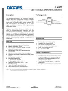
2 At -40 C to +125 C Low 10nV/ C Drift Low Noise: VP-P from DC to 10Hz 150dB AVOL, 140dB PSRR, 140dB CMRR High Gain-Bandwidth Product 1 MHz (MAX4238) (MAX4239) Ground-Sensing Input Rail-to-Rail Output (RL = 1k ) Low Power Consumption Reduces System Power Single to Supply Voltage Range 600 A Supply Current A Shutdown Mode Low Power Consumption Reduces System Power AEC-Q100 Qualified, Refer to Ordering Information for the List of /V Parts19-2424; Rev 10; 12/20 MAX4238/MAX4239360 STRAIN GAUGE18k 18k AIN5 VAV = 100 ADCMAX4238/MAX4239 Ultra-Low Offset/Drift, Low-Noise , Precision SOT23 AmplifiersTypical Application CircuitClick here to ask about the production status of specific part Voltage (VCC to GND).
3 6 VAll Other Pins ..(VGND - ) to (VCC + )Output Short-Circuit Duration (OUT shorted to VCC or GND) ..ContinuousContinuous Power Dissipation (TA = +70 C) 6-Pin Plastic SOT23 (derate C above +70 C) .. 8-Pin Plastic SO (derate C above +70 C) ..471mW 6-Pin TDFN-EP (derate above +70 C) ..1454mWOperating Temperature Range ..-40 C to +125 CJunction Temperature ..+150 CStorage Temperature Range ..-65 C to +150 CLead Temperature (soldering, 10s) ..+300 CSoldering Temperature (reflow) Lead(Pb)-Free Packages ..+260 C Packages Containing +240 CSO-8 PACKAGE CODES8+4/S8-4 Outline Number21-0041 Land Pattern Number90-0096 Thermal Resistance, Single-Layer Board:Junction to Ambient ( JA)170 C/WJunction to Case ( JC)40 C/WThermal Resistance, Multi-Layer Board:Junction to Ambient ( JA)132 C/WJunction to Case ( JC)38 C/WTDFN-6 PACKAGE CODET633+2 Outline Number21-0137 Land Pattern Number90-0058 Thermal Resistance, Single-Layer Board:Junction to Ambient ( JA)55 C/WJunction to Case ( JC)9 C/WThermal Resistance, Multi-Layer Board.
4 Junction to Ambient ( JA)42 C/WJunction to Case ( JC)9 C/WPackage Integrated 2 MAX4238/MAX4239 Ultra-Low Offset/Drift, Low-Noise , Precision SOT23 AmplifiersStresses beyond those listed under Absolute Maximum Ratings may cause permanent damage to the device. These are stress ratings only, and functional operation of the device at these or any other conditions beyond those indicated in the operational sections of the specifications is not implied. Exposure to absolute maximum rating conditions for extended periods may affect device Maximum Ratings( VCC , VCM = VGND = 0V, VOUT = VCC/2, RL = 10k connected to VCC/2, SHDN = VCC, TA = +25 C, unless otherwise noted.)
5 PARAMETERSYMBOLCONDITIONSMINTYPMAXUNITSI nput Offset VoltageVOS(Note 1) VLong-Term Offset Drift50nV/1000hrInput Bias CurrentIB(Note 2)1pAInput Offset CurrentIOS(Note 2)2pAPeak-to-Peak Input NoiseVoltageenP-PRS = 100 , to VP-PInput Voltage-Noise Densityenf = 1kHz30NV/ HzCommon-Mode InputVoltage RangeVCMI nferred from CMRR testVGND - - Rejection VCM VCC - (Note 1)120140dBPower-Supply Rejection VCC (Note 1)120140dBLarge-Signal Voltage VOUT VCC - (Note 1)RL = 10k VOUT VCC - (Note 1)RL = 1k 125145 Output Voltage SwingVOH/VOLRL = 10k VCC - VOH410mVVOL410RL = 1k VCC - VOH3550 VOL3550 Output Short-Circuit CurrentTo either supply40mAOutput Leakage Current0 VOUT VCC, SHDN = GND (Note 2) ASOT23-6 PACKAGE CODEU6FH+6/U6FH-6 Outline Number21-0058 Land Pattern Number90-0175 Thermal Resistance, Single-Layer Board:Junction to Ambient ( JA) C/WJunction to Case ( JC)75 C/WThermal Resistance, Multi-Layer Board.
6 Junction to Ambient ( JA) C/WJunction to Case ( JC)39 C/WPackage thermal resistances were obtained using the method described in JEDEC specification JESD51-7, using a four-layer board. For detailed information on package thermal considerations, refer to the latest package outline information and land patterns (footprints), go to Note that a + , # , or - in the package code indicates RoHS status only. Package drawings may show a different suffix character, but the drawing pertains to the package regardless of RoHS Information (continued) Integrated 3 MAX4238/MAX4239 Ultra-Low Offset/Drift, Low-Noise , Precision SOT23 AmplifiersElectrical Characteristics( VCC , VCM = VGND = 0V, VOUT = VCC/2, RL = 10k connected to VCC/2, SHDN = VCC, TA = +25 C, unless otherwise noted.)
7 PARAMETERSYMBOLCONDITIONSMINTYPMAXUNITSS lew RateVCC = 5V, CL = 100pF,VOUT = 2V ProductGBWPRL = 10k , CL = 100pF,measured at f = Stable Closed-LoopGainRL = 10k , CL = 100pF,phase margin = 60 MAX42381V/VMAX423910 Maximum Closed-Loop GainRL = 10k , CL = 100pF,phase margin = 60 MAX42381000V/VMAX42396700 Settling Time-1V (10 bit) (12 bit) (14 bit) (16 bit) Recovery TimeAV = 10(Note 4) (10 bit) (12 bit) (14 bit) (16 bit) TimeAV = (10 bit) (12 bit) (14 bit) (16 bit) Voltage RangeVCCI nferred by PSRR CurrentICCSHDN = VCC, no load, VCC = ASHDN = GND, VCC = Input Current0V V SHDN Integrated 4 MAX4238/MAX4239 Ultra-Low Offset/Drift, Low-Noise , Precision SOT23 AmplifiersElectrical Characteristics (continued)Note 1: Guaranteed by design.
8 Thermocouple and leakage effects preclude measurement of this parameter during production testing. Devices are screened during production testing to eliminate defective 2: IN+ and IN- are gates to CMOS transistors with typical input bias current of 1pA. CMOS leakage is so small that it is impractical to test and guarantee in production. Devices are screened during production testing to eliminate defective 3: Leakage does not include leakage through feedback 4: Overload recovery time is the time required for the device to recover from saturation when the output has been driven to either 5: Specifications are 100% tested at TA = +25 C, unless otherwise noted.
9 Limits over temperature are guaranteed by design.( VCC , VCM = GND = 0V, VOUT = VCC/2, RL = 10k connected to VCC/2, SHDN = VCC, TA = -40 C to +125 C, unless otherwise noted.) (Note 5)PARAMETERSYMBOLCONDITIONSMINTYPMAXUNIT SI nput Offset VoltageVOS(Note 1)TA = -40 C to +85 VTA = -40 C to +125 Offset DriftTCVOS(Note 1)10nV/ CCommon-Mode Input VoltageRangeVCMI nferred from CMRR testVGND- Rejection RatioCMRRVGND - VCM VCC (Note 1)TA = -40 C to +85 C115dBTA = -40 C to +125 C90 Power-Supply Rejection VCC (Note 1)120dBLarge-Signal Voltage GainAVOLRL = 10k , VOUT VCC - (Note 1)TA = -40 C to +85 C125dBTA = -40 C to +125 C95RL = 1k (Note 1)
10 VOUT VCC - ,TA = -40 C to +85 VOUT VCC - ,TA = -40 C to +125 C80 Output Voltage SwingVOH/VOLRL = 10k VCC - VOH20mVVOL20RL = 1k VCC - VOH100 VOL100 Output Leakage Current0V VOUT VCC, SHDN = GND(Note 3)2 ASupply Voltage RangeVCCI nferred by PSRR CurrentICCSHDN = VCC, no load, VCC = ASHDN = GND, VCC = Input Current0V VSHDN VCC2 AMaxim Integrated Offset/Drift, Low-Noise , Precision SOT23 AmplifiersElectrical Characteristics(VCC = 5V, VCM = 0V, RL = 10k connected to VCC/2, SHDN = VCC, TA = +25 C, unless otherwise noted.)MAX4238 GAIN AND PHASE vs. FREQUENCYMAX4238/39 toc09 FREQUENCY (Hz)GAIN AND PHASE (dB/DEGREES)1M100k10k1k-160-140-120-100- 80-60-40-20020406080-18010010 MVCC = 5 VGAIN = 40dBRL = 10k CL = 68pFMAX4238 GAIN AND PHASE vs.