Transcription of May 2020 MEDIUM-DUTY FRONT DRIVE STEER AXLES
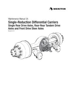
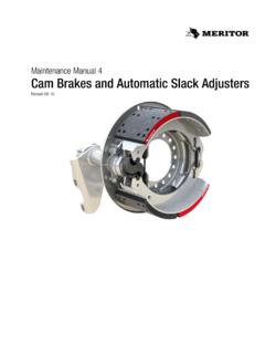
1 Maintenance Manual MM-0170 MEDIUM-DUTY FRONT DRIVE STEER AxlesMX-120 and MX-120-EVO SeriesApplies to 120 Standard and 120-HR High-Retardation CarriersRevised 02-17 Service NotesInformation contained in this publication was in effect at the time the publication was approved for printing and is subject to change without notice or liability. meritor Heavy Vehicle Systems, LLC, reserves the right to revise the information presented or to discontinue the production of parts described at any Maintenance Manual MM-0170 ( revised 02-17)About This ManualThis manual provides maintenance and service information for meritor MX-120 and MX-120-EVO Series MEDIUM-DUTY FRONT DRIVE STEER You and understand all instructions and procedures before you begin to service and observe all Warning and Caution hazard alert messages in this publication.
2 They provide information that can help prevent serious personal injury, damage to components, or your company s maintenance and service, installation, and diagnostics special tools when required to help avoid serious personal injury and damage to Alert Messages and Torque SymbolsWARNINGA Warning alerts you to an instruction or procedure that you must follow exactly to avoid serious personal injury and damage to Caution alerts you to an instruction or procedure that you must follow exactly to avoid damage to components.@ This symbol alerts you to tighten fasteners to a specified torque to Obtain Additional Maintenance, Service and Product InformationVisit Literature on Demand at to access and order additional the meritor OnTrac Customer Call Center at 866-668-7221 (United States and Canada); 001-800-889-1834 (Mexico).
3 Or email Tools, Supplies and Kits are Specified in This ManualContact meritor s Commercial Vehicle Aftermarket at and Non-Asbestos Fibers1 Section 1: Exploded ViewsMX-120 and MX-120-HR Series5MX-120-EVO Series9 Section 2: IntroductionOverviewMX Series MEDIUM-DUTY FRONT DRIVE STEER AxlesModel NomenclatureAxles11 Section 3: Removal and Disassembly - MX-120 and MX-120-HR SeriesRemovalWheel from the Drum18 Section 4: Removal and Disassembly - MX-120-EVO SeriesRemovalWheel from the Drum26 Section 5: Prepare Parts for AssemblyCleanGround and Polished PartsRough PartsAxle AssembliesDry Cleaned PartsCorrosion ProtectionCleaned PartsInspectionParts28 Repair or Replace Parts29 Applying Adhesive and Silicone Gasket MaterialSilicone (RTV) Gasket Material30 Section 6.
4 Assembly and Installation - MX-120 and MX-120-HR SeriesPrepare Parts for Assembly32 Check Steering Knuckle Turning TorqueInstallationAxle Shaft Through the Steering Knuckle33 AssemblySpindle, Brake Assembly and Dust Shield to the Steering Knuckle34 InstallationWheel Bearings Into the HubHub Onto the Axle35 AdjustmentWheel BearingsWheel Speed Sensors on Units Equipped with ABS36 InstallationDrive Flange and HubcapAssemblySlack Adjuster38 AdjustmentBrakes39 Section 7: Assembly and Installation - MX-120-EVO SeriesPrepare Parts for Assembly41 Check Steering Knuckle Turning TorqueInstallationAxle Shaft Through the Steering KnuckleAssemblySpindle, Brake Assembly and Dust Shield to the Steering Knuckle43 InstallationWheel Bearings Into the HubHub Onto the Axle44 AdjustmentWheel Bearings45 Wheel Speed Sensors on Units Equipped with ABSI nstallationDrive Flange and Hubcap46 AssemblySlack Adjuster47 AdjustmentBrakes48 Section 8.
5 AdjustmentInspectionAdjustmentFront Wheel Alignment49 Check and AdjustWheel Bearings50 Maximum Turn Angle51 Turning Radius AngleSteering Axis InclinationCamber Angle52 Caster Angle53 Measure and Adjust the Toe55 Section 9: TroubleshootingTroubleshootingFront DRIVE STEER Axle Troubleshooting57 Section 10: Lubrication and MaintenanceLubricationMagnets and Magnetic Drain IndicatorsCheck and Adjust the Axle Oil LevelDrain and Replace the Axle Oil58 Hub Check, Drain and Fill Procedures for DRIVE AXLES Equipped with Wheel-End Fill PlugsKnuckle King Pins59 Cross Tube End Assembly60 Wheel Bearings and Hub SealCamshaft Retainer Bushing and Cam Bushing61 FRONT DRIVE Axle Greasing Intervals and Specifications62 FRONT DRIVE Axle and Wheel End Oil Intervals and SpecificationsFront DRIVE STEER Axle Oil Change IntervalsEVO Lube Bath Wheel End Oil Change Intervals63 Lubricant SpecificationsMaintenanceInspection and Maintenance71 Section 11: SpecificationsMX-120 and MX-120HR Series73MX-120-EVO Series75 Section 12.
6 Special ToolsTool DrawingsAxle Shaft Seal Driver76 Hub Seal Driver77 Bushing DriverAsbestos and Non-Asbestos FibersiMeritor Maintenance Manual MM-0170 ( revised 02-17)Figure ASBESTOS FIBERS WARNING The following procedures for servicing brakes are recommended to reduce exposure to asbestos fiber dust, a cancer and lung disease hazard. Material Safety Data Sheets are available from meritor . Hazard SummaryBecause some brake linings contain asbestos, workers who service brakes must understand the potential hazards of asbestos and precautions for reducing risks. Exposure to airborne asbestos dust can cause serious and possibly fatal diseases, including asbestosis (a chronic lung disease) and cancer, principally lung cancer and mesothelioma (a cancer of the lining of the chest or abdominal cavities).
7 Some studies show that the risk of lung cancer among persons who smoke and who are exposed to asbestos is much greater than the risk for non-smokers. Symptoms of these diseases may not become apparent for 15, 20 or more years after the first exposure to , workers must use caution to avoid creating and breathing dust when servicing brakes. Specific recommended work practices for reducing exposure to asbestos dust follow. Consult your employer for more Work Practices1. Separate Work Areas. Whenever feasible, service brakes in a separate area away from other operations to reduce risks to unprotected persons. OSHA has set a maximum allowable level of exposure for asbestos of f/cc as an 8-hour time-weighted average and f/cc averaged over a 30-minute period.
8 Scientists disagree, however, to what extent adherence to the maximum allowable exposure levels will eliminate the risk of disease that can result from inhaling asbestos dust. OSHA requires that the following sign be posted at the entrance to areas where exposures exceed either of the maximum allowable levels:DANGER: ASBESTOSCANCER AND LUNG DISEASE HAZARDAUTHORIZED PERSONNEL ONLYRESPIRATORS AND PROTECTIVE CLOTHINGARE REQUIRED IN THIS AREA. 2. Respiratory Protection. Wear a respirator equipped with a high-efficiency (HEPA) filter approved by NIOSH or MSHA for use with asbestos at all times when servicing brakes, beginning with the removal of the Procedures for Servicing Enclose the brake assembly within a negative pressure enclosure.
9 The enclosure should be equipped with a HEPA vacuum and worker arm sleeves. With the enclosure in place, use the HEPA vacuum to loosen and vacuum residue from the brake As an alternative procedure, use a catch basin with water and a biodegradable, non-phosphate, water-based detergent to wash the brake drum or rotor and other brake parts. The solution should be applied with low pressure to prevent dust from becoming airborne. Allow the solution to flow between the brake drum and the brake support or the brake rotor and caliper. T he wheel hub and brake assembly components should be thoroughly wetted to suppress dust before the brake shoes or brake pads are removed.
10 Wipe the brake parts clean with a If an enclosed vacuum system or brake washing equipment is not available, employers may adopt their own written procedures for servicing brakes, provided that the exposure levels associated with the employer s procedures do not exceed the levels associated with the enclosed vacuum system or brake washing equipment. Consult OSHA regulations for more Wear a respirator equipped with a HEPA filter approved by NIOSH or MSHA for use with asbestos when grinding or machining brake linings. In addition, do such work in an area with a local exhaust ventilation system equipped with a HEPA NEVER use compressed air by itself, dry brushing, or a vacuum not equipped with a HEPA filter when cleaning brake parts or assemblies.