Transcription of MCP2561/2 Data Sheet - Northwestern University
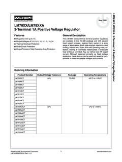
1 2013 Microchip Technology 1 MCP2561/2 Features: Supports 1 Mb/s Operation Implements ISO-11898-5 Standard Physical Layer Requirements Very Low Standby Current (5 A, typical) VIO Supply Pin to Interface Directly to CAN Controllers and Microcontrollers with to I/O SPLIT Output Pin to Stabilize Common Mode in Biased Split Termination Schemes CAN Bus Pins are Disconnected when Device is Unpowered- An Unpowered Node or Brown-Out Event will Not Load the CAN Bus Detection of Ground Fault:- Permanent Dominant Detection on TXD- Permanent Dominant Detection on Bus Power-on Reset and Voltage Brown-Out Protection on VDD and VIO Pin Protection Against Damage Due to Short-Circuit Conditions (Positive or Negative Battery Voltage) Protection Against High-Voltage Transients in Automotive Environments Automatic Thermal Shutdown Protection Suitable for 12V and 24V Systems Meets or exceeds stringent automotive design requirements including Hardware Requirements for LIN, CAN and FlexRay Interfaces in Automo-tive Applications , Version , May 2012 High-Noise Immunity Due to Differential Bus Implementation High ESD Protection on CANH and CANL, Meets IEC61000-4-2 greater 8 kV Available in PDIP-8L, SOIC-8L and 3x3 DFN-8L Temperature ranges:- Extended (E): -40 C to +125 C- High (H): -40 C to +150 CDescription:The MCP2561/2 is a Microchip Technology Inc.
2 Secondgeneration high-speed CAN transceiver. It serves as aninterface between a CAN protocol controller and thephysical two-wire CAN device meets the automotive requirements forhigh-speed (up to 1 Mb/s), low quiescent current,electromagnetic compatibility (EMC) and electrostaticdischarge (ESD).Package TypesMCP2561/2 Family MembersMCP2562 PDIP, SOICVDDVSSRXDCANHCANL12348765 VIOSTBYTXDMCP2561 PDIP, SOICVDDVSSRXDCANHCANL12348765 SPLITSTBYTXDMCP25613x3 DFN*VDDVSSRXDCANHCANL12348765 SPLITSTBYTXDEP9 MCP25623x3 DFN*VDDVSSRXDCANHCANL12348765 VIOSTBYTXDEP9* Includes Exposed Thermal Pad (EP); see Ta b l e 1 - 2 DeviceFeatureDescriptionMCP2561 Split pinCommon mode stabilizationMCP2562 VIO pinInternal level shifter on digital I/O pinsNote: For ordering information, see the Product Identification System section on page CAN TransceiverMCP2561/2DS25167B-page 2 2013 Microchip Technology DiagramNote 1:There is only one receiver implemented.
3 The receiver can operate in Low-Power or High-Speed :Only MCP2561 has the SPLIT :Only MCP2562 has the VIO pin. In MCP2561, the supply for the digital I/O is internally connected to ControlThermalProtectionPORUVLOD igital I/OSupplyVIO(3)VSSSTBYP ermanentDominant DetectVIOVIOModeControlVDD/2 SPLIT(2 )Wake-UpFilterCANHCANLCANHCANLR eceiverLP_RX(1)HS_RX 2013 Microchip Technology 3 MCP2561 OVERVIEWThe MCP2561/2 is a high-speed CAN, fault-tolerantdevice that serves as the interface between a CANprotocol controller and the physical bus. TheMCP2561/2 device provides differential transmit andreceive capability for the CAN protocol controller, andis fully compatible with the ISO-11898-5 standard. It willoperate at speeds of up to 1 , each node in a CAN system must have adevice to convert the digital signals generated by aCAN controller to signals suitable for transmission overthe bus cabling (differential output).
4 It also provides abuffer between the CAN controller and the high-voltagespikes that can be generated on the CAN bus byoutside Control BlockThe MCP2561/2 supports two modes of operation: Normal StandbyThese modes are summarized in Ta b l e 1 - MODEN ormal mode is selected by applying a low-level to theSTBY pin. The driver block is operational and can drivethe bus pins. The slopes of the output signals on CANHand CANL are optimized to produce minimalelectromagnetic emissions (EME).The high speed differential receiver is active. MODEThe device may be placed in Standby mode byapplying a high-level to the STBY pin. In Standbymode, the transmitter and the high-speed part of thereceiver are switched off to minimize powerconsumption. The low-power receiver and the wake-upfilter block are enabled in order to monitor the bus foractivity.
5 The receive pin (RXD) will show a delayedrepresentation of the CAN bus, due to the Transmitter FunctionThe CAN bus has two states: Dominant andRecessive. A Dominant state occurs when thedifferential voltage between CANH and CANL isgreater than VDIFF(D)(I). A Recessive state occurswhen the differential voltage is less than VDIFF(R)(I).The Dominant and Recessive states correspond to theLow and High state of the TXD input pin, , a Dominant state initiated by another CANnode will override a Recessive state on the CAN FunctionIn Normal mode, the RXD output pin reflects the differ-ential bus voltage between CANH and CANL. The Lowand High states of the RXD output pin correspond to theDominant and Recessive states of the CAN bus, ProtectionCANH and CANL are protected against battery short-circuits and electrical transients that can occur on theCAN bus.
6 This feature prevents destruction of thetransmitter output stage during such a fault device is further protected from excessive currentloading by thermal shutdown circuitry that disables theoutput drivers when the junction temperature exceedsa nominal limit of +175 C. All other parts of the chipremain operational, and the chip temperature is low-ered due to the decreased power dissipation in thetransmitter outputs. This protection is essential toprotect against bus line short-circuit-induced 1-1:MODES OF OPERATIONModeSTBY PinRXD PinLOWHIGHN ormalLOWBus is dominantBus is recessiveStandbyHIGHWake-up request is detectedNo wake-up request detectedMCP2561/2DS25167B-page 4 2013 Microchip Technology Dominant Detection The MCP2561/2 device prevents two conditions: Permanent dominant condition on TXD Permanent dominant condition on the busIn Normal mode, if the MCP2561/2 detects anextended Low state on the TXD input, it will disable theCANH and CANL output drivers in order to prevent thecorruption of data on the CAN bus.
7 The drivers willremain disabled until TXD goes Standby mode, if the MCP2561/2 detects anextended dominant condition on the bus, it will set theRXD pin to Recessive state. This allows the attachedcontroller to go to Low-Power mode until the dominantissue is corrected. RXD is latched High until aRecessive state is detected on the bus, and thewake-up function is enabled conditions have a time-out of ms (typical).This implies a maximum bit time of s( kHz), allowing up to 18 consecutive dominant bitson the Reset (POR) and Undervoltage DetectionThe MCP2561/2 has undervoltage detection on bothsupply pins: VDD and VIO. Typical undervoltage thresh-olds are for VIO and 4V for VDD. When the device is powered on, CANH and CANL remain in a high-impedance state until both VDD andVIO exceed their undervoltage levels.
8 In addition,CANH and CANL will remain in a high-impedance stateif TXD is Low when both undervoltage thresholds arereached. CANH and CANL will become active onlyafter TXD is asserted High. Once powered on, CANHand CANL will enter a high-impedance state if the volt-age level at VDD or VIO drop below the undervoltagelevels, providing voltage brown-out protection duringnormal Normal mode, the receiver output is forced toRecessive state during an undervoltage condition. InStandby mode, the low-power receiver is only enabledwhen both VDD and VIO supply voltages rise abovetheir respective undervoltage thresholds. Once thesethreshold voltages are reached, the low-power receiveris no longer controlled by the POR comparator andremains operational down to about on the VDDsupply ( MCP2561/2 ). The MCP2562 transfers data tothe RXD pin down to 1V on the VIO DescriptionsTable 1-2 describes the 1-2: MCP2561/2 PINOUTMCP25613x3 DFNMCP2561 PDIP, SOICMCP25623x3 DFNMCP2562 PDIP, SOICS ymbolPin Function11 1 1 TXDT ransmit Data Input22 2 2 VSSG round33 3 3 VDDS upply Voltage44 4 4 RXDR eceive Data Output55 SPLITC ommon Mode Stabilization - MCP2561 only 5 5 VIOD igital I/O Supply Pin - MCP2562 only6666 CANLCAN Low-Level Voltage I/O7777 CANHCAN High-Level Voltage I/O8888 STBYS tandby Mode Input9 9 EPExposed Thermal Pad 2013 Microchip Technology 5 MCP2561 DATA INPUT PIN (TXD)The CAN transceiver drives the differential output pinsCANH and CANL according to TXD.
9 It is usuallyconnected to the transmitter data output of the CANcontroller device. When TXD is Low, CANH and CANLare in the Dominant state. When TXD is High, CANHand CANL are in the Recessive state, provided thatanother CAN node is not driving the CAN bus with aDominant state. TXD is connected to an internal pull-upresistor (nominal 33 k ) to VDD or VIO, in the MCP2561or MCP2562, SUPPLY PIN (VSS)Ground supply VOLTAGE PIN (VDD)Positive supply voltage pin. Supplies transmitter DATA OUTPUT PIN (RXD)RXD is a CMOS-compatible output that drives High orLow depending on the differential signals on the CANHand CANL pins, and is usually connected to thereceiver data input of the CAN controller device. RXD isHigh when the CAN bus is Recessive, and Low in theDominant state. RXD is supplied by VDD or VIO, in theMCP2561 or MCP2562, PIN (MCP2561 ONLY)Reference Voltage Output (defined as VDD/2).
10 The pinis only active in Normal mode. In Standby mode, orwhen VDD is off, SPLIT PIN (MCP2562 ONLY)Supply for digital I/O pins. In the MCP2561, the supplyfor the digital I/O (TXD, RXD and STBY) is internallyconnected to LOW PIN (CANL)The CANL output drives the Low side of the CANdifferential bus. This pin is also tied internally to thereceive input comparator. CANL disconnects from thebus when MCP2561/2 is not HIGH PIN (CANH)The CANH output drives the high-side of the CANdifferential bus. This pin is also tied internally to thereceive input comparator. CANH disconnects from thebus when MCP2561/2 is not MODE INPUT PIN (STBY)This pin selects between Normal or Standby mode. InStandby mode, the transmitter, high speed receiver andSPLIT are turned off, only the low power receiver andwake-up filter are active. STBY is connected to aninternal MOS pull-up resistor to VDD or VIO, in theMCP2561 or MCP2562, respectively.