Transcription of MD0106E GE series - SAH electronics
1 MA0106E081216 Safety InformationModel and Suffix codePower SupplyDimensions & Panel CutoutCounter / TimerGE SeriesThank you for purchasing HANYOUNG NUX CO,.Ltd. Product. Please check whether the prouduct you purchased is the exactly same as you ordered. Before using product, please read instruction maunal MANUALHEAD OFFICE 1381-3, Juan-Dong, Nam-Gu Incheon, KoreaTEL: (82-32)876-4697 FAX : (82-32)876-4696 Before you use, read safety precautions carefully, and use this productproperly. The precautions described in this manual contains importantcontents related with safety; therefore, please follow the instructionsaccordingly. The precautions are composed of DANGER, WARNINGand not touch or contact the input/output terminals because they maycause electric If there is a possibility of an accident caused by errors ormalfunctions of this product, install external protection circuit toprevent the This product does not contain an electric switch or fuse, so the userneeds to install a separate electric switch or fuse externally.
2 (Fuserating : 250 V A)3. To prevent defection or malfunction of this product, supply properpower voltage in accordance with the To prevent electric shock or devise malfunction of this product, donot supply the power until the wiring is Since this product is not designed with explosion-protectivestructure, do not use it at any place with flammable or explosive Do not decompose, modify, revise or repair this product. This maycause malfunction, electric shock or Reassemble this product while the power is off. Otherwise, it maycause malfunction or electric It you use the product with methods other than specified by themanufacturer, there may be bodily injuries or property Due to the danger of electric shock, use this product installed onto apanel while an electric current is The contents of this manual may be changed without prior Before using the product you have purchased, check to make surethat it is exactly what you Check to make sure that there is no damage or abnormality of theproduct during Do not use this product at any place with corrosive(especiallynoxious gas or ammonia)
3 Or flammable Do not use this product at any place with direct vibration or Do not use this product at any place with liquid, oil, medicalsubstances, dust, salt or iron contents. (Pollution level 1 or 2)7. Do not polish this product with substances such as alcohol or Do not use this product at any place with excessive inductiontrouble, static electricity or magnetic Do not use this product at any place with possible thermalaccumulation due to direct sunlight or heat Install this product at place under 2,000m in When the product gets wet, the inspection is essential becausethere is danger of an electric leakage or If there is excessive noise from the power supply, using insulatingtransformer and noise filter is recommended.
4 The noise filter mustbe attached to a panel grounded, and the wire between the filteroutput side and power supply terminal must be as short as If gauge cables are twisted closely, the effect on noise may occur. 14. Do not connect anything to the unused After checking polarity of terminal, connect wires at the correct When this product is connected to a panel, use a circuit breaker orswitch approved with IEC847-1 or Install the circuit breaker or switch at near place for convenient For the continuous and safe use of this product, the periodicalmaintenance is Some parts of this product have limited life span, and others arechanged by their The warranty period for this product including parts is one year ifthis product is properly When the power is on, the preparation period of contact output isrequired.
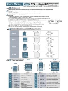
5 In case of use for signals of external interlock circuit, usewith a delay (W) (H) (L) (W) (H) (L) (W) (H) (L) (W) (H) (L) PRESETBATCHTOTAL (Indicator) 4 : 9999 (4 digit) GE3,GE7:Not available6 : 999999 (6 digit) 1 stage2 stage Twin timer Support100 V - 240 V V - 60 V Batch CounterGE3GE4GE6GE7PT4612 ADAppearanceTypeDigitStagePower supplyDuring the first 100 after power input and first 200 after poweropening, it is consider as ascend and descend time of internal power andexternal output power. Therefore, it does not operate during unstableperiod in order to prevent from malfunction which is caused by unstableoutput operation of external sensorSupply signal only after 100 following the power input.
6 Supply power only after 200 following the power shutdown. GE7GE4[Unit : mm]SpecificationConnection Diagram GE6GE4-P1GE4-P2GE6-P1GE6-P2GE3-P1 NPN InputPanel Same asaboveMore than 8245 32 Same asaboveMore than 60 More than 90 More than 130 More than 60 More than 57 Same asaboveSame asabove+ + 0+ 0+ 0+ 0+ 0GE6GE3GE7a1a2L1L2 ModelFND heightCounting speed and inputMemory for SHOT outputTimer operationDielectric StrengthInsulation ResistanceWithstanding noiseProtection structureAmbient temperatureAmbient humidityWeightCertificate100 - 240 V (50 - 60 ) 10 24 - 60 V / (50 - 60 ) 10 Max. 9 VAMax. 9 VAMax. V V 13 10 8 Min output12 V (5 %) 200 V (5 %) 100 s [OUT1, OUT2(OUT)]1a (OUT1), 1c (OUT2)NO contact: 250V 3A resistance load, NC contact: 250V 2A resistance loadNPN 2 points(OUT, )Comparative cycle: repeated setup error less than 5 for every 2 Stable time: 100 stable time when POWER ON2000 V 50 - 60 for 1 minuteMin 100 (Based on 500 V )Square wave noise by noise simulator (1pulse per 16ms) 2 (Power supply input terminal)10 - 55 (for 1 min period) double amplitude each direction for 10 minutes10 - 55(for 1 min period) double amplitude each direction for 2 hours100 (About 10G)300 (About 30G)Min.
7 100 thousand times (250 V 2 A resistance load)Min 1 million timesIP65 (Front part only) -20 ~ 65 (Non freezing state)-10 ~ 55 , 35 ~ 85 % (No freezing or decondensation) 1 cps / 30 cps / 1 K cps / 10 K cps Contact/Non-contact10 years (Nonvolatile memory)CP1, CP2, RESET, BATCH RESET (exclude TOTAL) 4inputs[H] level 4 - 30 V , [L] level 0 - 2 V Internal pull up/pulldown resistance connection due to NPN/PNP setupExternal reset Min. input signal range: select among / 1ms / 20 msSTART, INHIBIT, RESET Min. input signal range: select either 1ms / 20 msGE4GE6GE3GE71 step2 stepCapacity1 step2 stepCapacity1c (OUT)1a (OUT)1c (OUT)NPN 2 points(OUT1,OUT2)Open collector 30 V 100 Max.
8 G g g g If you want to modify Input and output type, plesae contact HANYOUNG sales officeName of Each Section Maximum Coefficient Speed GE3-P2GE3GE6GE4GE7GE7-P1GE7-P2 Coefficient Input 1(CP1) / Inhibit Input (INHIBIT) TerminalWith using counter, it is used as coefficient input or coefficient inhibit Process time become HOLD when timer function is selectedCoefficient Input 2(CP2) / Start (START) TerminalWith using counter, it is used as coefficient input or coefficient inhibitWith using timer, it can be used as SIGNAL ON START, SIGNAL ONE START. (Refer to output mode operation)(SIGNAL ON START: Timer operates only with the continuous input.)
9 (SIGNAL ONE START: Timer operates only with the supply of Input 1 Pulse.)BAT. RESETThis is used as BATCH, RESET during the use of counter / timer. RESET This initializes the coefficient value and current time during the use of counter / timer. OUT, OUT2 : This is used as the counter / timer comparative output. : Batch Counter Output (1 Stage Setup Type) OUT1( ): Select between 2 Stage Setup Output and Batch Counter Output (2 Stage Setup Type) Coefficient display (RED FND)Display coefficient value (counter), time process value (timer), batch coefficient value and setup display (GREEN FND)Display setup value (counter), setup time (timer), batch setup value, instant output setup (batch setup is 0 in Timer) and setup contentsSET1, SET2 (SET), BAT Indicates the status of coefficient section and setup section (BAT lamp corresponds to batch status.)
10 TIM (Timer)This flashes when the timer progresses and remains lighted when the devicestops from inhibit input or reset.(It is indicated in Change Mode of the device during TIM/TTWIN setup.)CNT (Counter)This is indicated during 1 CNT/2 CNT setup in Change Mode of the , OUT2(OUT), (Output Action Indication) lights up when the batch setup value is set. (OUT1 Output) lights up and outputs when the device operates with the instant outputwhere the batch setup value is 0 (timer). CP1, CP2, RST: Verification of Input Status. (Exclusively for TOTAL) LOCK:Key Lock (KEY LOCK) Action IndicationThis lights up during Lock Setup. This key is for function setup Mode Entry and Mode change.