Transcription of ME 111: Engineering Drawing
1 ME 111: Engineering DrawingLecture # 14 (10/10/2011)Development of surfaces 1 ~psr/Indian Institute of Technology GuwahatiGuwahati 781039 Development of surfacesAdevelopmentistheunfold/unrolled flat / plane figureof a 3-D pattern, the planemay showthe true size of eacharea of the the pattern is cut, it can berolledorfoldedbackintotheoriginal of development of surfaces are: Parallel line development Radial line development Triangulation development Approximate development Parallel linedevelopmentuses parallel lines toconstruct theexpanded pattern of each three-dimensional shape.
2 The methoddivides the surface into a series of parallel lines to determine theshape of a : Prism, Cylinder. Radial line developmentuses lines radiating froma central pointtoconstruct theexpandedpatternof : Cone, Pyramid. Triangulationdevelopmentsaremadefrompoly hedrons, single-curvedsurfaces, : Tetrahedronand other polyhedrons. Inapproximate development, joining, thepart is stretchedor distortedtoobtain the final of DevelopmentsAtrue developmentis one in which no stretching or distortion of thesurfaces occurs and every surface of the development is the samesize and shape as the corresponding surface on the 3-D polyhedrons and single curved surfacesPolyhedrons are composed entirely of plane surfaces that can beflattened true size onto a plane in a connected consecutivepairsofstraight-line elements in the same developmentis one inwhich stretching or distortion resulting flat surfaces are not surfaces do not
3 Produce truedevelopments,becausepairsofconsecuti ve straight-line elements donot forma double-curved surfaces , such asaspheredonotproducetruedevelopments, becausetheydonotcontain any straight fromcommon solids that arecomposed of parallel lateral edgesor ispositionedsuchthat oneelement lies on the development the development base and top of the cylinder are circles,with a circumference equal to the length ofthe elementsof thecylinder areparallel andareperpendicular to the base and the , all elementsareparallel and any perpendicular section appears as astretch-out line that is perpendicular to the Radial-line the development, all the elements ofthe figure become radial lines that havethe vertex as their cone is then unrolled until it is flat on the development end of all the elements is at the vertex of the cone.
4 The otherends describe a curved base of the cone is a circle, with a circumference equal to thelength of the curved Triangulation developments:Madefrompolyhedrons,single- curvedsurfaces, any ruled surface intoa series of triangular each side of every triangle is true length, any number of trianglescan be connected into a flat plane to forma developmentTriangulationfor singlecurvedsurfacesincreasesinaccuracyt hrough the use of smaller and more numerous of wrappedsurfaces produces onlyapproximate of those developments are used for double curved surfaces , such as sections of the Approximate developmentsThematerial of theobject isthenstretchedthroughvariousmachineappl icationstoproducethedevelopment of the developmentsDevelopments of objects with parallel elements or parallel lateral edges begins by constructing a stretch-out line that is parallel to a right section of the object and is therefore, perpendicular to the elements or lateral edges.
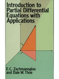
5 Development of a right rectangular prismIn the front view, all lateral edges of the prismappear parallel to eachother and are true length. The lateral edges are also true length in thedevelopment. The length, or the stretch-out, of the development isequal to the true distance around a right section of the 1. To start the development, draw the stretch-out line in the front view, along the base of the prism and equal in length to the perimeter of the another line in the front view along the top of the prism and equal in length to the stretch-out line. Draw vertical lines between the ends of the two lines, to create the rectangular pattern of the prism.
6 The fold line on the pattern by transferring distances along thestretch-out line in length to the sides of the prism, 1-2, 2-3, 3-4, , dashed vertical lines frompoints 2, 3, and 4 to represent the bottomandtopsurfaces of the prismtothe development, takingmeasurements fromthe top view. Add the seamto one end of the developmentand the bottomand of a truncated prismStep1:Drawthe stretch-out line in the front view, along the base of theprismand equal in length to the perimeter of the the fold lines on the pattern along the stretch-out line equal inlength to the sides of the prism, 1-2, 2-3, 3-4, and perpendicular construction lines at each of these points.
7 Project the points 1, 2, 3, and 4 from the front viewStep 2: Darken lines 1-2-3 and 4-1. Construct the bottom and top, as shown and add the seam to one end of the development and the top and bottom Development of a right circular cylinderStep1. In the front view, drawthe stretch-out line aligned with thebase of the cylinder and equal in length to the circumference of thebase each end of this line, construct vertical lines equal in length to theheight of the Add the seamto the right end of the development, and addthe bottomand top of a truncated right circular cylinderThe top circular view of the cylinder is divided into a number of equalparts, stretch-out line, equal in length to the circumference of the circle.
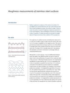
8 Is aligned with the base in the viewand is divided into 12 equalparts fromwhich vertical lines are intersection points in the are projected into the , wherethe projected lines intersect the angled edge viewof the truncatedsurfaceof thecylinder. Theseintersectionpointsareinturnprojecte d into the intersections betweenthese projections andthe vertical linesconstructedfromthestretch-out linearepointsalongthecurverepresenting the top line of the truncated of a truncated right circular cylinderDevelopment of a right circular coneTo begin this development, use a true-length element of the cone as the radius for an arc and as one side of the development.
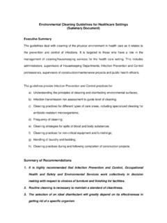
9 A true- length element of a right circular cone is the limiting element of the cone in the front view. Draw an arc whoselength is equal to the circumference of the base of the cone. Draw another line from the end of the arc to the apex and draw the circular base to complete the :A cone of base diameter 40 mmand slant height 60 mmis kept on the groundonits base. AnAIPinclinedat 45 tothe HPcuts the cone throughthemidpoint of the axis. Draw the Fig. Draw FV and TV as shown. Locate the Divide the TV into 12 equal parts and drawthe corresponding lateral lines( , generators) inFV.
10 Mark points p1 , p2 , p3 , .., p12 at the points Obtain the included angle of the sector. = (20/60)* 360 = 120 .4. DrawO 1 parallel and equal to o 7. Then drawsector O 1 1 Owith Oasa centre and included angle 120 .5. Divide the sector into 12 equal parts ( , 10 each). Drawlines O 2, O 3,O 4, .., O Project points p1 , p2 , p3 , .., p12 fromFVtocorrespondinglines indevelopment and mark points P1, P2, P3, .., P12 respectively. Join all thesepoints by a smooth freehand of Transition pieces used in industrySource : InternetTriangulation developmentEmployed to obtain the development of Transition PiecesTransition pieces are the sheet metal objects used for connecting pipes or openings either of different shapes of cross sections or of same cross sections but not arranged in identical joining a curvedcross sectionto a noncurvedcross section(e,g, Squaretoround, hexagontoround , square to ellipse, etc.)