Transcription of Measurement of Directly Designed Gears with …
1 GEARTECHNOLOGY January/February 2011 SummaryIn comparison with the traditional gear design approach based on preselected, typically standard generating rack parameters, the Direct gear Design method provides certain advantages for custom high-performance gear drives that include: increased load capacity, efficiency and lifetime; reduced size, weight, noise, vibrations, cost, etc. However, manufacturing such Directly Designed Gears requires not only custom tooling, but also customization of the gear mea-surement methodology. This paper presents definitions of main inspection dimensions and parameters for Directly Designed spur and helical, external and internal Gears with symmetric and asymmetric teeth.
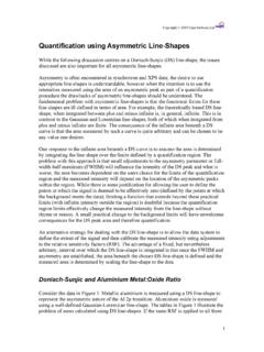
2 Measurement of Directly Designed Gears with Symmetric and asymmetric TeethDr. Alexander L. Kapelevich(This paper was first presented at the 2010 VDI International Conference on Gears VDI Wissensforum). a b Figure 1 gear tooth profile: a = external gear ; b = internal gear ; da = tooth tip circle diameter; db = base circle diameter; df = form circle diameter; d = reference circle diameter; S= circular tooth thickness at the reference diameter; a = involute profile (or pressure) angle at the reference diameter; v = involute intersection profile angle; n = number of teeth.
3 Subscripts d and c are for the drive and coast flanks of the asymmetric pgs 601/19/2011 10:38:08 January/February 2011 GEARTECHNOLOGY61continuedMeasurement Over (Between) Balls or PinsSpur Gears . The Direct gear Design method (Refs. 1 2) presents the gear tooth by two involutes of two base circles with the angular distance between them and tooth tip circle arc ( ). The equally spaced n teeth form the gear . The fillet between teeth is Designed independently, thus providing minimum bending-stress concentration and sufficient clear-ance with the mating tooth-tip in mesh.
4 If the two base circles are identical, the gear teeth are symmetric; if they are differ-ent, the teeth are asymmetric . Measurement over (between) balls or pins for spur Gears is defined based on the given: Number of teeth n Reference circle diameter d Involute profile angles at the reference diameter ad and ac; for symmetric Gears involute profile angle at the reference diameter a = ad = ac Circular tooth thickness at the reference diameter S gear tooth-tip diameter da Initially selected ball or pin diameter D can be adjusted based on the calculation results.
5 The relation between angles vd and vc, and ad and ac is: (1) where: dbd = d x cosad and dbc = d x vd and vc are defined from equations: For external gear :(2)For internal gear :(3)where: inv(x) = tan(x) x is involute function and x is involute profile angle in radians. The centers of the ball or the pin are located on the diameter dp (Fig. 2), which is: (4)where the angles apd and apc are defined by equations (Ref. 3): For external gear :(5)For internal gear :(6)The ball or pin touches the gear tooth in the points Td and Tc. They should be always located on the involute flanks.
6 This condition is described by the following equation: For external Gears :(7) and:(8)For internal Gears :(9) and:(10) a b dbd =cos d==cos ccos dcos cdbddbc, inv( d)+ inv( c)= inv( d)+ inv( c)+2 x Sd, inv( d)+ inv( c)= inv( d)+ inv( c)+ Sd,2 x n ,dp=dbdcos pd=dbccos pc, inv( pd)+ inv( pc)= inv( d) + inv( c)+ +Ddbd,Ddbc 2 n inv( pd)+ inv( pc)= inv( d) + inv( c) Ddbd Ddbc arccosdfddbd td arccosdadbddbd =cos d==cos ccos dcos cdbddbc, inv( d)+ inv( c)= inv( d)+ inv( c)+2 x Sd, inv( d)+ inv( c)= inv( d)+ inv( c)+ Sd,2 x n ,dp=dbdcos pd=dbccos pc, inv( pd)+ inv( pc)= inv( d) + inv( c)
7 + +Ddbd,Ddbc 2 n inv( pd)+ inv( pc)= inv( d) + inv( c) Ddbd Ddbc arccosdfddbd td arccosdadbddbd =cos d==cos ccos dcos cdbddbc, inv( d)+ inv( c)= inv( d)+ inv( c)+2 x Sd, inv( d)+ inv( c)= inv( d)+ inv( c)+ Sd,2 x n ,dp=dbdcos pd=dbccos pc, inv( pd)+ inv( pc)= inv( d) + inv( c)+ +Ddbd,Ddbc 2 n inv( pd)+ inv( pc)= inv( d) + inv( c) Ddbd Ddbc arccosdfddbd td arccosdadbddbd =cos d==cos ccos dcos cdbddbc, inv( d)+ inv( c)= inv( d)+ inv( c)+2 x Sd, inv( d)+ inv( c)= inv( d)+ inv( c)+ Sd,2 x n ,dp=dbdcos pd=dbccos pc, inv( pd)+ inv( pc)= inv( d) + inv( c)+ +Ddbd,Ddbc 2 n inv( pd)+ inv( pc)= inv( d) + inv( c) Ddbd Ddbc arccosdfddbd td arccosdadbddbd =cos d==cos ccos dcos cdbddbc, inv( d)+ inv( c)= inv( d)+ inv( c)+2 x Sd, inv( d)+ inv( c)= inv( d)+ inv( c)+ Sd,2 x n ,dp=dbdcos pd=dbccos pc, inv( pd)+ inv( pc)= inv( d) + inv( c)+ +Ddbd,Ddbc 2 n inv( pd)+ inv( pc)= inv( d) + inv( c) Ddbd Ddbc arccosdfddbd td arccosdadbddbd =cos d==cos ccos dcos cdbddbc, inv( d)
8 + inv( c)= inv( d)+ inv( c)+2 x Sd, inv( d)+ inv( c)= inv( d)+ inv( c)+ Sd,2 x n ,dp=dbdcos pd=dbccos pc, inv( pd)+ inv( pc)= inv( d) + inv( c)+ +Ddbd,Ddbc 2 n inv( pd)+ inv( pc)= inv( d) + inv( c) Ddbd Ddbc arccosdfddbd td arccosdadbddbd =cos d==cos ccos dcos cdbddbc, inv( d)+ inv( c)= inv( d)+ inv( c)+2 x Sd, inv( d)+ inv( c)= inv( d)+ inv( c)+ Sd,2 x n ,dp=dbdcos pd=dbccos pc, inv( pd)+ inv( pc)= inv( d) + inv( c)+ +Ddbd,Ddbc 2 n inv( pd)+ inv( pc)= inv( d) + inv( c) Ddbd Ddbc arccosdfddbd td arccosdadbd ; arccosdfcdbc tc arccosdadbc arccosdadbd tdarccosdfddbd arccosdadbc tcarccosdfcdbc M = dp + D;M = dp.
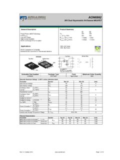
9 Cos + ; arccosdfcdbc tc arccosdadbc arccosdadbd tdarccosdfddbd arccosdadbc tcarccosdfcdbc M = dp + D;M = dp . cos + Figure 2 Ball or pin position: a = external gear ; b = internal gear ; D = ball or pin diameter; P = center of the ball or pin; apdand apc = involute profile angles at the center of the ball or pin; dp = ball or pin center location diameter; Td and Tc = contact points of the ball or pin with the tooth drive and coast tooth flanks; atd and atc = involute profile angles at the contact points. ; arccosdfcdbc tc arccosdadbc arccosdadbd tdarccosdfddbd arccosdadbc tcarccosdfcdbc M = dp + D;M = dp.
10 Cos + Kappelevich pgs 611/19/2011 10:38:09 AM GEARTECHNOLOGY January/February 2011 Measurement over two balls or pins for the external gear is for even number of teeth (Fig. 3a): (11)For odd number of teeth (Fig. 3b): (12)The Measurement between two balls or pins for the inter-nal gear is for even number of teeth (Fig. 4a): (13) For odd number of teeth (Fig. 4b): (14)For inspection convenience the Measurement over balls or pins for external Gears should be M > da and the measure- a b ; arccosdfcdbc tc arccosdadbc arccosdadbd tdarccosdfddbd arccosdadbc tcarccosdfcdbc M = dp + D;M = dp.