Transcription of Mechanical design of pressure vessel by using PV …
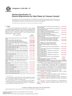
1 International Journal of Scientific and Research Publications, Volume 4, Issue 4, April 2014 1. ISSN 2250-3153. Mechanical design of pressure vessel by using PV-ELITE. software Vijay Kumar*, Pardeep Kumar**. *. Department of Mechanical Engineering, UIET, KUK, Haryana, India **. Department of Mechanical Engineering, UIET, KUK, Haryana, India Abstract- The safety factor of a pressure vessel is related to both the tensile stress and yield strength for material allowance. ASME code section VIII has fully covered these two on the construction code for pressure vessel . This code section addressed mandatory and non-mandatory appendixes requirement, specific prohibition, vessel materials, design , fabrication, examination, inspection, testing, certification, and pressure relief. Mechanical design of a horizontal pressure vessel based on this standard had been done incorporating PV ELITE.
2 Software. Analyses were carried out on head, shell, nozzle and pressure vessel saddle. The input parameters are type of material, pressure , temperature, diameter, and corrosion allowance. Analysis performed the calculations of internal and external pressure , design CODES. weight of the element, allowable stresses, vessel longitudinal stress check, nozzle check and saddle check. pressure vessels are always works under certain pressure and temperature along with contain sometime lethal substances Key words- pressure vessel , ASME section VIII division 1, which are hazardous for both human and environment. PV-ELITE, Mechanical design . Considering this, safety implications and hazards arising from the operation of pressure vessels, there is an obvious need to I. INTRODUCTION standardize engineering and fabrication practices.
3 To assure minimum safety standards, several design codes have prepared pressure vessels are leak proof containers, as the name implies, and developed. In Europe most widely National codes are: their main purpose is to contain a given medium under pressure GERMANY - AD MARKBLATTER, BRITISH BS1500, BS. and temperature. pressure vessels are commonly used in industry 1515, ITLAY CCPA. to carry both liquid and gases under required pressure and In the United States and Canada, the most widely used Standards temperature limit. This pressure and temperature comes from an are the ASME boiler and pressure vessel code, published by external source or by the application of heat from a direct or American Society of Mechanical Engineers (ASME). ASME. indirect source or any combination of them. They may be of any section VIII deals with the design for pressure vessels, materials shape and size ranging beer canes, automobile tires or gas specification, fabrication, opening and reinforcement, testing and storage tank, to more sophisticated ones encountered in marking, inspection and other mandatory or non mandatory engineering applications.
4 pressure vessels; commonly have the appendixes. Section VIII contains three divisions, covering the cylindrical, spherical, ellipsoidal, conical or a combination of different pressure ranges: these shapes. However, some pressure vessels are named after Division 1: up to 3000 psi (200 bar). the type of function they required to perform. For example, the Division 2: up to 10000 psi (690 bar). distillation column is a vessel used in oil and petroleum refining Division 3: above 10000 psi (above 690 bar ). process. The heat exchanger used in many types of industries to transfer heat from one fluid to another fluid, acted as same. Also, ASME section VIII, Division 1, deals with conventional pressure reactor is a vessel , which is used for chemical reaction of vessels means design by rule, while division 2, deals with contained substance.
5 The material comprising the vessel is stringent alternative rules means design by analysis, and division subjected to pressure loading and hence stresses from all 3 deals with design of Nuclear Equipment. direction. The normal stresses resulting from this pressure are Vessels failure can be grouped into four major functions of diameter of the elements under consideration, the categories, which describe why a vessel failure occurs. Failures shape of the pressure vessel as well as the applied pressure . also grouped into types of failures, which describe how the failure occurs mean each failure contains its failure history, why and how it occurs. There are many reasons of vessels failure such as: Improper material selection, defected material. International Journal of Scientific and Research Publications, Volume 4, Issue 4, April 2014 2.
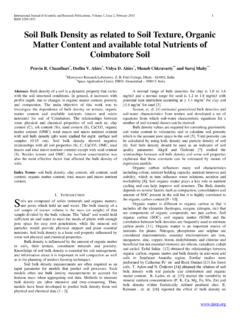
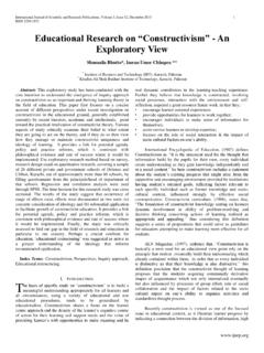
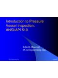
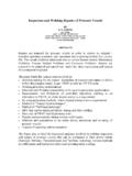
6 ISSN 2250-3153. Incorrect design data, incorrect or inaccurate design design design method or process, inadequate shop testing. Temp. pressure Internal 100 C Internal 225 Psi Improper fabrication process, poor quality control, External 35 C External 15 Psi insufficient fabrication process including welding, heat treatment and forming methods. Table 1. design Input Data III. RESULTS. Horizontal pressure vessel is drawn as per element input data and the icon for each element can be found easily. The input parameters for each element also type in the suitable bar as can be seen on screen. Once all the elements were connected, the pressure vessel would be as shown in figure. After completion of design in PV ELITE, design analysis has been carried out which Fig. 2. Failure of pressure vessel during hydro Test. shows results for each component as per input data.
7 The results have shown safe and failure conditions as per ASME standard. In order to meet a safe design , a designer must be familiar with Result analysis has been carried out in the form of equations, the above mentioned failure and its causes. There have a few main factors to design safe pressure vessel . This study is substitution and code references. focusing on analyzing the safety parameters for allowable working pressure . Allowable working pressures are calculated by using PV ELITE software which compile with the ASME section VIII, rules for construction pressure vessels. The objectives of the study is to design pressure vessel according to input data and analyze the safety parameters of each component for its allowable working pressure using ; PV ELITE software. II. design INPUT DATA. component units components Units Shell Nozzle Length 400 CM NPS 300 MM.
8 Internal dia 1500 MM Schedule 80. Thickness 12 MM Material SA106B. Material SA515GR70 Length 200 MM Figure 3. Mechanical design of pressure vessel by PV ELITE. 3 MM. Dished end Nozzle Internal pressure Calculation Results: (both side) NPS 300 MM ASME Code, Section VIII, Division 1, 2007. Type Ellipsoidal Schedule 80 Elliptical Head (Both ends) SA-516 70, UCS-66 Curve. B at 100. Internal dia 1500 MM Material SA106B C. Material SA515GR70 Length 200 MM Thickness Due to Internal pressure [Tr]: 3 MM =(P*(D+2*CA)*K)/(2*S* *P) Appendix 1-4(c) =. ( *( +2* )* )/(2* * Nozzle Saddle * ) = + = mm Width 250 MM Max. All. Working pressure at Given Thickness [MAWP]:=. NPS 300 MM Wear plate 400 MM (2*S*E*(T-Ca))/(K*(D+2*Ca)+ *(T-Ca)) per Appendix 1-4. Schedule 80 width (c)=(2* * *( ))/( *( +2* )+0. Material SA106B Contact angle 120 deg.)
9 2*( ))= kgf/cm . Length 200 MM Wear plate Maximum Allowable pressure , New and Cold [MAPNC]:=. thickness 12 MM (2*Sa*E*T)/(K*D+ *T) per Appendix 1-4 (c)=. (2* * * )/( * + * ) =. kgf/cm . Actual stress at given pressure and thickness [Sact]: = (P*(K*(D+2*CA) + *(T-CA)/(2*E*(T- CA))=( *( *( +2* )+ *( )))/(2*. *( )) = kgf/cm . International Journal of Scientific and Research Publications, Volume 4, Issue 4, April 2014 3. ISSN 2250-3153. Percent Elongation per UCS-79 SELECTION OF POSSIBLE REINFORCING PADS: (75*tnom/Rf)*(1-Rf/Ro) % Diameter Thickness Based on given Pad Thickness: mm Cylindrical Shell From 20 To 30 SA-516 70 , UCS-66 Curve. B Based on given Pad Diameter: mm at 100 C Based on Shell or Nozzle Thickness: SHELL mm Thickness Due to Internal pressure [Tr]: Reinforcement Area Required for Nozzle [Ar]: =. = (P*(D/2+Ca))/(S* *P) per UG-27 (c)(1) = (Dlr*Tr+2*Thk*Tr*(1-fr1)) UG-37(c)=.)
10 ( *( + ))/( * * ) = ( * +2*( )* *( )) =. + = mm cm . Max. All. Working pressure at Given Thickness [MAWP]:= Areas per but with DL = Diameter Limit, DLR =. (S*E*(T-Ca))/((D/2+Ca)+ *(T-Ca)) per UG-27 (c)(1) Corroded ID: =( * *( ))/(( + )+ * )= Area Available in Shell [A1]:= (DL-Dlr)*(ES*(T-Cas)-Tr)- kgf/cm 2*(Thk-Can)*(ES*(T-Cas)-Tr)*(1-fr1) = ( Maximum Allowable pressure , New and Cold [MAPNC]:= )*( *( ) )-2*( (SA*E*T)/(D/2+ *T) per UG-27 (c)(1) )*( *( ) )*( ) = cm . =( * * )/( + * )= Area Available in Nozzle Wall, no Pad [A2np]:= ( 2 *. kgf/cm min(Tlnp,ho) ) * ( Thk - Can - Trn ) * fr2 = ( 2 * min( Actual stress at given pressure and thickness [Sact]:= , ) ) * ( - - ) * ) = cm . (P*((D/2+CA)+ *(T-CA)))/(E*(T-CA)) = Area Available in Nozzle Wall, with Pad [A2wp]:= ( 2 * Tlwp)*(. ( *(( + )+ *( )))/( *( )) Thk - Can - Trn )* fr2= ( 2 * ) * ( - - = kgf/cm ) * ) = cm.