Transcription of Mechanical Joint Assembly - ebaa.com
1 Mechanical Joint InstallationMechanical Joint AssemblyFrom AWWA C600-101. Clean the socket and the plain end. Lubrication and additional cleaning should be provided by brushing both the gasket and plain end with soapy water or an approved pipe lubricant meeting the requirements of ANSI/AWWA C111 just prior to slipping the gasket onto the plain end for Joint Assembly . Place the gland on the plain end with the lip extension toward the plain end, followed by the gasket with the narrow edge of the gasket toward the plain end [The gasket provided may have been the EBAA-Seal Improved Mechanical Joint Gasket. This gasket is bi-directional and has no front or back. The use of a pipe wall stiffening insert is required on High Density Polyethylene pipe.].3. Push the gland toward the socket and center it around the pipe with the gland lip against the gasket.
2 Insert bolts and hand-tighten nuts. Make deflection after Joint Assembly but before tightening Tighten the bolts to the normal range of bolt torque as indicated in Table 1 while at all times maintaining approximately the same distance between the gland and the face of the flange at all points around the socket. This can be accomplished by partially tightening the bottom bolt first, then the top bolt, next the bolts at either side, finally the remaining bolts. Repeat the process until all bolts are within the appropriate range of torque. In large sizes (30 48 in. [762 1,219 mm]), five or more repetitions may be required. The use of a torque-indicating wrench will facilitate this Insert the pipe into the socket and press the gasket firmly and evenly into the gasket recess.
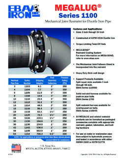
3 Keep the Joint straight during : In cold weather it is preferable to warm the gasket to facilitate Assembly of the 1 - Mechanical Joint Bolt TorquesPipe SizeBolt SizeRange of lbN m376 1645 - 6061 - 814 - 24102 - 610 1975 - 90102 - 12230 - 36762 - 914125100 - 120136 -16342 - 481,067 1,2191 32120 - 150163 - 2031115 - ENote: Dimensions are in inches and are subject to change without Joint Sizes and SpecificationsDimensions for the Standardized Mechanical JointANSI/AWWA and 2013 EBAA Iron, - ENote: Dimensions are in inches and are subject to change without Pipe Size ACross Sectional Area of Pipe (sq. in.)GlandBolt HolesBellC110 Fittings(Thick Wall)C153 Fittings(Thin Wall) 3 3 3 3 3 3 3 + 4 + 4 + 4 +.
4 4 + 4 + + , + , 6 + , 6 The Cross Sectional Area of the pipe is based on the outside diameter of the pipe. The MEGALUG Series 1142 and 1148 requires and are supplied with 8 inch t-BoltsAt EBAA Iron, all of our products are tested with a minimum safety factor of 2:1. Therefore, all of our products have been tested to at least twice the rated pressure of the restraint device. To determine the amount of force held by a Joint restraint device at a certain pressure, obtain the cross sec-tional area of the pipe size from the table above and multiply that number by the desired pressure. The result will be the equivalent dead end thrust load resisted by the restraint at the chosen Example - The dead end thrust of a 12 inch Joint at 350 PSI would be:Thrust = x 350 = 47,915 pounds of forceArea = D2/4 Where = and D = Pipe