Transcription of Mechanically Jointed Rodless Cylinder Series MY1
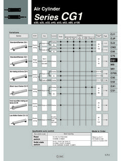
1 Series MY1 Mechanically Jointed Rodless CylinderAircushionStrokeadjustingUnitEnd lockSidesupportFloatingbracketMade to OrderIntermediatestrokeLong strokeHelical insert threadDust seal bandNBR liningHolder mountingbracketCentralizedpipingStandard pipingBasic typeSlide bearing guide typeCam follower guide typeLinear guide typeHigh rigidity/Linear guide typeMY1 BMY1 MMY1 CMY1 HSeriesGuide typePiping typeMY1HT32 4050 638010016 20 25 Bore size (mm)10(3)(2)P. 951P. 975P. 995P. 1015P. 1039 LargeHigh Series VariationsSeries Variations(1)Note 1) 10 is available with central piping only.
2 Note 2) 10 is available with rubber bumper 3) Availability for made-to-order differs, depending on the size and the rigidity/Linear guide typeSeries MY1 HTLinear guide typeSeries MY1 HCam follower guide typeSeries MY1 CSlide bearing guide typeSeries MY1 MBasic typeSeries MY1 BMY1 BMY1 MMY1 CMY1 HMY1 HTMY1 WMY2 CMY2H MY3 MMY3 AMY3 BIndividual-X D- -X 2:19 PM Page 943 Slide bearing typeLinear guide typeCam follower guide typeHigh rigidity/Linear guide type Basic type Wide variations from 10 to 100 Simple guide typethat can mount aworkpiece against moment,compatible with longstrokes !
3 " # $ " ! Linear guideHeavy loaded workpiecescan be accommodated by usingtwo linear a linearguide to achievehigh repeatabilityStroke availability Stroke availability Centralized pipingCentralized pipingSide supportSide supportInterchangeabilityInterchangeabil ityStroke adjusting unitStroke adjusting unit % & ' ' ( Adjusting bolt Low load shock absorber +Adjusting bolt (L unit) Heavy-loaded shock absorber + Adjusting bolt (H unit) 2:19 PM Page 944 Centralizedpiping type(Standard)Linear guide type MY1H10 Basic type MY1B10 Using eyeboltsExtremely easy to maintainHigh rigidity/Linear guide type MY1HT50/63 It is possible to replace cylinderswith a workpiece being mounted.)
4 The stroke adjusting unit (H unit) does not protrude above the table 27 mm Stroke adjusting unit can be mounted !" Allows fine stroke controlLock pin Even when equipped with a floatingbracket, the heightis only Eyebolt mounting threads are standard for convenient instal-lation. Same dimensions as standard Possible to lock either on one side or on both WMY2 CMY2H MY3 MMY3 AMY3 BIndividual-X D- -X 2:20 PM Page 945 Selection Flow ChartOperating ConditionsTentative Selection of Cylinder ModelMY1B: Basic typeMY1M: Slide bearing guide typeMY1C: Cam follower guide typeMY1H: Linear guide typeMY1HT.
5 High rigidity/Linear guide typeLoad massm m maxDetermination of allowable moment[ ] 1 Examination of cushioningmechanism at stroke endType Lstroke adjusting unitAir cushionRubber bumperType Hstroke adjusting unitExternalcushioning unit Examination of port variations and auto switch mounting (type)Model selectedReview the operating larger Cylinder guide larger Cylinder guide type or Centralized piping typeNGNGNGNGNGNGOKOKOKOKOKOKS elect a guide suitable for the applicationStandards for Tentative Model SelectionCylinder modelMY1 BMY1 MMY1 CMY1 HMY1 HTGuide typeBasic typeSlide bearing guide typeCam follower guide typeLinear guide typeHigh rigidity/Linear guide typeStandards for guide selectionGuaranteed accuracy not required, generally combined with separate guideSlide table accuracy approx.
6 Mm (2)Slide table accuracy approx. mm (2)Slide table accuracy of mm or less required (2)Slide table accuracy of mm or less required (2)M3: YawingSeries MY1 Model Selection 1 Following are the steps for selecting the most suitable Series MY1 to your for relatedallowable valuesRefer to P. to P. to P. to P. to P. : RollingM1: PitchingNote 1) These accuracy values for each guide should be used only as a guide during selection. Please contact SMC when guaranteed accuracy for MY1C/MY1H is 2) Accuracy here means displacement of the slide table (at stroke end) when 50% of the allowable moment shown in the catalog is applied.
7 (reference value).m: Load mass (kg)V: Speed (mm/s)P: Operating pressure (MPa)Mountingorientation:Accuracy:Select larger Cylinder size. For external cushioning unit, the installation of a suitable cushioning mechanism near the load center of gravity by the customer's side is is possible to select all models of Mechanically Jointed Rodless Cylinder ( Series MY1 ) according to the step indicated to the separate instruction manual for further details. If you have any questions, please contact 2:20 PM Page 946M3 EFEM3Y aTypes of Moment Applied to Rodless CylindersMultiple moments may be generated depending on the mounting orientation, load, and position of the center of and MomentsStatic MomentDynamic Moment M3: Yawing M2: RollingM1.
8 Pitchingm3 x gxM2zM3 XZym1 x gM1 XxM2 Yym2 x gM1 XxM2Ym4 x gM1ZM3zyYM1M1 EFEZ amn x gHorizontal mountingWall mountingVertical mountingCeiling mountingm1m2m3m4 Note)M1M2M3m1 x g x Xm1 x g x Y m2 x g x Xm2 x g x Y m3 x g x Zm3 x g x Xm4 x g x Z m4 x g x a x x mn x g x FE x ZDynamic moment M2E is not generated. x FE x Y1313g: Gravitational accelerationg: Gravitational acceleration, a: Average speed, : Damper coefficientmn x gNote) m4 is a mass movable by thrust. Use to times the thrust (differs depending on the operating speed) as a guide for actual load (m)Static momentHorizontalmountingCeilingmountingW allmountingVerticalmountingMountingorien tationHorizontalmountingCeilingmountingW allmountingVerticalmountingDynamic load (FE)Dynamic momentNote) Regardless of the mounting orientation, dynamic moment is calculated with the formulae Jointed Rodless Cylinder Series MY1MY1 BMY1 MMY1 CMY1 HMY1 HTMY1 WMY2 CMY2H MY3 MMY3 AMY3 BIndividual-X D- -X 2.
9 20 PM Page : Workpiece (500 g)Wc: MHL2-16D1 (795 g)Wb: MGGLB25-200 ( kg)MY1H40-500Wa: Connection plate t = 10 (880 g) Mounting Orientation1. Horizontalmounting2. Wallmounting3. Ceilingmounting4. VerticalmountingWaWbWcWdWorkpiece kgMassmn65 mm150 mm150 mm150 mmX-axisXn0 mm0 mm111 mm210 mmY-axisYnCenter of gravityZ-axisZnn = a, b, c, d 5 mmm3M2Zm3 Mass and Center of Gravity for Each WorkpieceP. 978P. 998P. 1042 Calculation of Guide Load FactorSeries MY1 Model Selection 2 Following are the steps for selecting the most suitable Series MY1 to your Operating Conditions Operating Cylinder MY1H40-500 Average operating speed a 300 mm/s Mounting orientation Wall mounting Cushion Air cushion( = 1/100)2.
10 Load Blocking3. Composite Center of Gravity Calculation4. Calculation of Load Factor for Static LoadFor actual examples of calculation for each orientation, refer to the pages = mn= + + + = kgX= x (mn x xn) = ( x 65 + x 150 + x 150 + x 150) = mmY= x (mn x yn) = ( x 0 + x 0 + x 111 + x 210) = mmZ= x (mn x zn) = ( x 5 + x + x + x ) = mm m3: Massm3 max (from (1) of graph MY1H/m3) = 50 (kg) Load factor 1 = m3/m3 max = = : MomentM2 max (from (2) of graph MY1H/M2) = 50 (N m) M2 = m3 x g x Z = x x x 10 3 = (N m)Load factor 2 = M2/M2 max = = 2.

