Transcription of MECHANICS OF A VARIABLE AREA FLOWMETER …
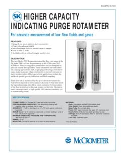
1 FLOWMETERS. MECHANICS OF A VARIABLE area FLOWMETER . A VARIABLE area FLOWMETER (Figure 1) is a The accuracy of a VARIABLE area FLOWMETER device used for measuring the flow of is contingent on both its operating pres- gases or gas mixtures. Typically, it consists sure and temperature. Gases at higher of a glass metering tube (1) which is inter- pressures will be compressed, and there- nally tapered such that the inside diame- fore a greater volume of gas will pass ter at the bottom of the tube is smaller through the same given area . Similarly, than that at the top. A float or floats (2) gases at higher temperatures will be less placed inside the tube are contained by dense, and less gas will pass through a float stops (3) inserted into the inlet and given area . Therefore, all VARIABLE area outlet of the tube. The tube assembly is flowmeters are calibrated at specific tem- fitted between the two end blocks (6 & 7) perature and pressure conditions gener- and sealed by packing gaskets (4).
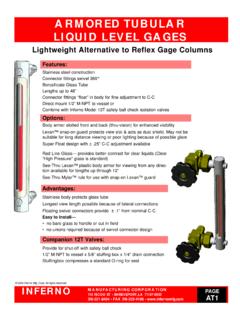
2 The ally at normal temperature (70 F) and FLOWMETER assembly is held together by pressure ( psia). front, back and side plates (10, 11 & 12). Once assembled, the FLOWMETER tube is tightened against the packing gaskets via a seal spindle (5) to ensure leak free oper- ation. Flowmeters may also be equipped with a metering valve (13) which adds the 1. Metering Tube Assembly capability of controlling flow rate. 2. Float 3. Float Stops 8. As gas enters the FLOWMETER tube, the float 4. Packing Gaskets & Grommets 9. is lifted from the zero position at the bot- 5. Seal Spindle & O-Rings tom of the tube. The float (Figure 2) rises 6. End Block (Outlet). to a point where the area surrounding the 7. End Block (Inlet) 5 6. float is sufficient to allow unrestricted flow 8. Inlet & Outlet Adaptors 5. of gas. The greater the flow of gas, the 9. Adaptor O-Rings higher the float will rise. 10. Front Plate 5. By knowing the variables involved (service 11. Back Plate gas, pressure, temperature, weight of 12.)
3 Side Plates 13. Metering Valve Assembly 4. float, tube diameter, etc.), the height of the float can be directly correlated to the 4. flow of gas with relatively good accuracy. 3. Generally, the tube is inscribed with a 2. scale allowing the user to read the float 11. 12. position. The scale may be direct reading in flow units such as standard liters per minute (slpm) or standard cubic feet per 1. hour (scfh). It may also be in a linear mea- surement such as millimeters (mm) which would require a calibration chart for cross referencing the linear measurement to a 3. corresponding flowrate. 4. 10 4 12. 8. 9. 7. 13. FIGURE 1, VARIABLE area FLOWMETER 48 ADVANCED Specialty Gas Equipment FLOWMETER SELECTION. FLOWMETERS. In selecting a FLOWMETER , the following 5. Repeatability: In many gas processes, items should be taken into consideration: the ability to duplicate flow measure- ments over time is more important than 1. Materials Compatibility: As with all the absolute accuracy of the readings.
4 The gas handling equipment, care must be repeatability specification shown for each taken to ensure that the materials used to FLOWMETER refers to the degree to which a construct the FLOWMETER are compatible meter will repeat a previous flow reading. with the service gas. Each of the flow- In general, VARIABLE area flowmeters have meters shown in this catalog is provided very good repeatability, many as high as with a list of its Materials of Construction. of full scale. This information should be used with the gas compatibility data provided under 6. Metering Valves: Flowmeters only Technical Information (page 140). measure flow. If adjustments to flow rates are required, a FLOWMETER equipped with a 2. Pressure and Temperature Ratings: metering valve should be selected. The FLOWMETER must be capable of handling pressures and temperatures required by the particular application. Maximum operating pressures and temperatures are provided for each FLOWMETER under Specifications.
5 Front View Top View 3. Measuring Range: Flowmeters have ;;;;;;;;;;. ;;; ;; ;;;. ;;;;;;;;;;. ; ; ; ;. specific measuring ranges associated with Outlet Maximum Flow them. These ranges will vary depending on the FLOWMETER model as well as the tube and float combination selected. A. ;. ; ;. ; ;. ;;; ;. Obviously, the specific FLOWMETER chosen must be capable of measuring in the flow Float range required by the process. In general, for the best accuracy, it is suggested that ;. ;. Top View at Point A. the FLOWMETER be sized for operation in the upper part of its range. 4. Accuracy: The FLOWMETER should be ;. accurate to the degree required by the application. Accuracy specifications are listed for each of our flowmeters. Generally, Moderate Flow ;. this will be 5% or 10% of full scale (although the Series 150 flowmeters also have an optional 1% full scale calibra- tion available.). ; B. ;. ;. Full scale accuracy means that the accuracy specification is based on the FLOWMETER 's Top View at Point B.
6 Maximum capacity. For example, a meter ;. with a measuring range of 1 10 slpm and an accuracy specification of 10% will have an actual accuracy of 1 slpm across its entire range that is, 10% of the ;. ;. maximum capacity of 10 slpm. Zero Flow C. ;. ;. Inlet ;. ;. Top View at Point C. FIGURE 2, VARIABLE area FLOWMETER Principle of Operation ADVANCED Specialty Gas Equipment 49. FLOWMETERS. 65 MM, DIRECT READING, VARIABLE area . FLOWMETERS (SERIES 50 AND 50K). Series 50 flowmeters offer an economical means of measuring gas or liquid flow at low pressures where 10% accuracy is acceptable. They are suitable for plant and general laboratory applications. These flowmeters are direct reading for air; however, approximate flow ranges for other gases are listed in the Tube Selection Table on the following page. STANDARD FEATURES SPECIFICATIONS. Ribbed Tubes stabilize float and Maximum Operating Pressure improve accuracy and readability. and Temperature: Borosilicate Glass Tubes allow operating Series 50: 200 psig at 250 F.
7 Temperatures up to 250 F (100 F for Series 50K: 150 psig at 100 F. Series 50K). Minimum Operating Temperature: 32 F. Threaded Fittings with Locking Nuts Accuracy: 10% of full scale from 10%. (Standard on Series 50) permit front to 100% of range panel mounting.* Series 50 FLOWMETER Repeatability: Within of full scale Unique Valve Design allows bubble- Tube Graduations: Standard cubic tight shutoff. centimeters per minute or standard Availability of Aluminum, Stainless Steel liters per minute of Air depending upon or Kynar Construction provides a wide range. See Tube Selection Tables. material selection for maximum gas Scale Length: 65 mm compatibility. Inlet and Outlet Connections: Series 50: 1 8" NPT female OPTIONAL FEATURES Series 50K: 1 4" NPT female Baseplate with Leveling Screws permits Approximate Weight: lb bench use. Aluminum Bezel permits flush panel MATERIALS OF CONSTRUCTION. mounting. Tubes: Borosilicate Glass with float stops Inlet Filter traps foreign matter, extends of Teflon.
8 FLOWMETER life and reduces maintenance. Floats: Borosilicate Glass, Type 316. * Series 50K Flowmeters may be front panel mount- Stainless Steel or Carboloy as specified ed using predrilled holes on rear of FLOWMETER and in Tube Selection Tables self-tapping screws. End Blocks: See Table I. Inlet/Outlet Adaptors: See Table I. Side Plates: Aluminum Back Plate: White Plastic FM 4711. Front Plate: Clear Plastic Optional Panel Mounting Bezel Seals and Packing: Viton (other materials available on special order). Valve: Type 316 Stainless Steel TABLE I. Inlet/Outlet Series Part No. End Blocks Material Adaptor Material 50 FM4350-( ) Aluminum Aluminum 50 FM4360-( ) Type 316 Stn. Stl. Type 316 Stn. Stl. 50K FM4451-( ) Kynar None Where ( ) is indicated above, complete the part number by inserting applicable tube number from Tube Selection Table below. Example: FM4350-5. Order by complete part number. 50 ADVANCED Specialty Gas Equipment FLOWMETERS. OPTIONAL EQUIPMENT.
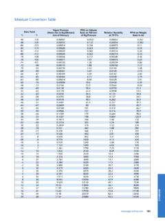
9 Equipment Part No. Baseplate FM4702. Inlet Filter, 2 micron Aluminum FM4741. Type 316 Stainless Steel (Series 50) FM4746. Type 316 Stainless Steel (Series 50K) SG6113. Aluminum Bezel for Flush Panel Mounting FM4711. Replacement Metering Valves Flowmeters with Tube Numbers FM4340 FM4344 0202-4113 (L). Flowmeters with Tube Numbers FM4345 FM4346 0202-4114 (M). Flowmeters with Tube Numbers FM4347 FM4349 0202-4115 (H). Replacement Tubes See Table Below TUBE SELECTION TABLES FOR SERIES 50 AND 50K FLOWMETERS. Flow rates shown are at 70 F and psia. Air Argon* Carbon Dioxide* Helium*. Tube No. Float Material (Actual Graduations) (Approx. Range) (Approx. Range) (Approx. Range). 0 Glass 50 sccm 43 sccm 61 sccm 47 sccm 1 Glass 85 sccm 71 sccm 104 sccm 79 sccm 2 Glass 40 440 sccm 38 375 sccm 36 355 sccm 52 513 sccm 3 316 Stn. Stl. 100 950 sccm 81 808 sccm 77 767 sccm slpm 4 Glass slpm slpm slpm slpm 5 316 Stn. Stl. slpm slpm slpm slpm 6 Glass 7 slpm slpm slpm slpm 7 316 Stn.
10 Stl. 13 slpm slpm slpm slpm 8 316 Stn. Stl. 24 slpm slpm slpm slpm 9 Carboloy 44 slpm slpm slpm 103 slpm Hydrogen* Nitrogen* Oxygen* Replacement Tubes Tube No. (Approx. Range) (Approx. Range) (Approx. Range) and Packing Part No. 0 105 sccm 51 sccm 45 sccm FM4340. 1 178 sccm 87 sccm 93 sccm FM4341. 2 slpm 45 449 sccm 41 411 sccm FM4342. 3 slpm 97 969 sccm 88 884 sccm FM4343. 4 slpm slpm slpm FM4344. 5 slpm slpm slpm FM4345. 6 slpm slpm slpm FM4346. 7 slpm slpm slpm FM4347. 8 slpm slpm slpm FM4348. 9 155 slpm slpm slpm FM4349. * Series 50 flow tubes are directly calibrated for air at 70 F and psia. Flow rates shown for other gases are for reference purposes only. Flow capacities for gases not listed may be obtained by contacting your Advanced Representative. ADVANCED Specialty Gas Equipment 51. FLOWMETERS. 150 MM, VARIABLE area FLOWMETERS. (SERIES 150 AND 150K). Series 150 flowmeters offer an accurate yet economical means of measuring gas or liquid flow at low pressures and over a wide range of flow rates.