Transcription of Mechanics of Materials 13-1 - Valparaiso University
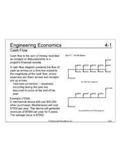
1 Professional Publications, of MaterialsStress- strain Curve for Mild SteelProfessional Publications, of MaterialsDefinitions Hooke s Law Shear Modulus: stress : strain : Poisson s Ratio: Normal stress or strain = Shear stress = || to the surface ! " to the surfaceProfessional Publications, of MaterialsDefinitionsUniaxial Load and DeformationThermal DeformationProfessional Publications, of MaterialsStress and StrainThin-Walled TanksHoop stress :Axial stress :Professional Publications, of MaterialsStress and StrainTransformation of AxesProfessional Publications, of MaterialsStress and StrainFive simplified steps to construct Mohr s the applied stresses ( x, y, xy). a set of - the the radius (or max) Mohr s circle. ! "c=12("x+"y).Professional Publications, of MaterialsStress and StrainFor examples 1 and 2, use the following 1 (FEIM)The principal stresses ( 2, 1) are most nearly(A) 62 400 kPa and 14 400 kPa(B)84 000 kPa and 28 000 kPa(C)70 000 kPa and 14 000 kPa(D)112 000 kPa and 28 000 kPaProfessional Publications, of MaterialsStress and StrainThe center of Mohr s circle is at !
2 "max=(30000 kPa)2+(24000 kPa)2=38419 kPa ! "1="c#$max=(#24000 kPa#38419 kPa)=#62419 kPa ! "2="c+#max=($24000 kPa+38419 kPa)=14418 kPaTherefore, (D) is the Pythagorean theorem, the radius of Mohr s circle ( max) is: ! "c=12("x+"y)=12(#48000 kPa+0)=#24000 kPaProfessional Publications, of MaterialsStress and StrainExample 2 (FEIM):The maximum shear stress is most nearly(A)24 000 kPa(B)33 500 kPa(C)38 400 kPa(D)218 000 kPaTherefore, (C) is the previous example problem, the radius of Mohr s circle ( max) was ! "max=(30000 kPa)2+(24000 kPa)2 ! =38419 kPa(38400 kPa)Professional Publications, of MaterialsStress and StrainGeneral strain ! Note that "x is no longer proportional to # Publications, of MaterialsStress and StrainStatic Loading Failure TheoryMaximum Normal stress : A material fails if Or ! "#St ! "#ScThis is true of brittle ductile Materials :Maximum ShearDistortion Energy (von Mises stress ) !
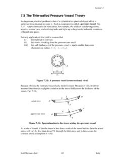
3 Tmax=max"1#"22,"1#"32,"2#"32$ % & & ' ( ) ) >Syt2 ! " # =12#1$#2()2+#1$#3()2+#2$#3()2% & ' ( ) * >SytProfessional Publications, of MaterialsStress and StrainTorsion For a body with radius r beingstrained to an angle , the shearstrain and stress are: ! "=rd#dz ! "=G#=Grd$dz For a body with polar moment ofinertia (J), the torque (T) is: ! T=Gd"dzr2dAA#=GJd"dzThe shear stress is: ! "#z=GrTGJ=TrJ For a body, the general angulardisplacement ( ) is: ! "=TGJdz0L# For a shaft of length (L), the totalangular displacement ( ) is:Torsional stiffness:Professional Publications, of MaterialsStress and StrainHollow, Thin-Walled ShaftsProfessional Publications, of MaterialsBeamsProfessional Publications, of MaterialsBeamsLoad, Shear, and Moment RelationsLoad:Shear:For a beam deflected to a radius of curvature ( ), the axial strain at adistance (y) from the neutral axis is !
4 "x=#y/$.Professional Publications, of MaterialsBeamsShear and Bending Moment DiagramsExample 1 (FEIM):Draw the shear and bending moment diagrams for the following Publications, of MaterialsBeamsShear is undefined at concentrated force points, but just short of x = 12 m ! Rl+Rr=100Nm" # $ % & ' 16 m()=1600 NRl=(8)(Rr(4)=0 Therefore, Rl = N and Rr = NSo the shear diagram is: ! From 0 m to 12 m, V=Rl"100Nm# $ % & ' ( x= N"100Nm# $ % 0 m < x < 12 m ! V(12")= N"100Nm# $ % & ' ( (12 m)=" N ! V=1600 N"100Nm# $ % 12 < x ) 16 m ! From 12 m to 16 m, V=V(12")+Rr"(100 N)(x"12)Professional Publications, of MaterialsBeamsThe bending moment is the integral of the shear. ! M=Sdx012"+Sdx12x"=#800+1600 N#100 Nmx$ % & ' ( ) 012"dx ! ="800 N#m+1600 N()x"50Nm$ % & ' ( ) x2$ % & ' ( ) 12xM = 50x2; 0 m < x < 12 m ! M="800 N#m+1600 N()x"50Nm$ % & ' ( ) x2"1600 N()12 m()+50Nm$ % & ' ( ) 12 m()2 !))
5 M="12800 N#m+1600 N()x"50Nm$ % & ' ( ) x2 ! 12 m<x"16 mOr, let the right end of the beam be x = 0 m ! Then, S="100Nm# $ % "4m<x)0 m ! M=Sdxx0"=#100Nm$ % & ' ( ) x0"x=#50Nm$ % & ' ( ) x2 Professional Publications, of MaterialsBeamsThe bending moment diagram is:Professional Publications, of MaterialsBeamsExample 2 (FEIM):The vertical shear for the section at the midpoint of the beam shown is(A) 0(B) (C) P(D) none of theseDrawing the force diagram and the shear diagram,Therefore, (A) is correct. ! 12 PProfessional Publications, of MaterialsBeamsExample 3 (FEIM):For the shear diagram shown, what is the maximum bending moment? Thebending moment at the ends is zero, and there are no concentrated couples.(A) 8 kN m(B) 16 kN m(C) 18 kN m(D) 26 kN mStarting from the left end of the beam, areas begin to cancel after 2 m. Startingfrom the right end of the beam, areas begin to cancel after 4 m.
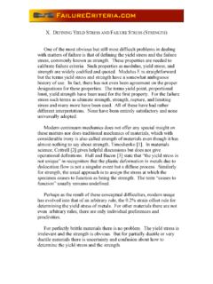
6 The rectangle onthe right has an area of 16 kN m. The trapezoid on the left has an area of(1/2)(12 kN + 14 kN) (2 m) = 26 kN m. The trapezoid has the largest , (A) is Publications, of MaterialsBeamsBending StressDeflectionShear StressNote: Beam deflection formulas are given in the NCEES Handbook forany situation that might be on the Publications, of MaterialsBeamsExample (FEIM):Find the tip deflection of the beam shown. EI is 106 N m2, theload is 11 379 N/m, and the beam is m the NCEES Handbook: ! "=woL48EI=11379Nm# $ % & ' ( m()48() )106 N*m2()= mProfessional Publications, of MaterialsColumnsBeam-Columns (Axially Loaded Beams)Maximum and minimum stresses in an eccentrically loaded column:Professional Publications, of MaterialsColumnsEuler s FormulaCritical load that causes a long column to buckle:r = the radius of gyrationk = the end-resistant coefficientkl = the effective length = slenderness ratio !
7 LrProfessional Publications, of MaterialsColumnsElastic strain Energy: strain energy per unit volume for tension.