Transcription of MECHANICS OF MATERIALS
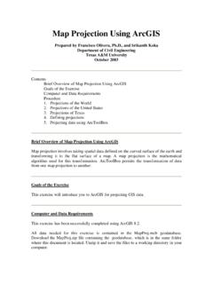
1 76 MECHANICS OF MATERIALSUNIAXIAL STRESS-STRAINS tress-Strain Curve for Mild Steel The slope of the linear portion of the curve equals the modulus of Strain = L/Lo, where = engineering strain (units per unit) L = change in length (units) of memberLo = original length (units) of memberPercent Elongation% Elongation = LL100o#DcmPercent Reduction in Area (RA)The % reduction in area from initial area, Ai, to final area, Af , is:%RA = AAA100iif#-eo Shear Stress-Strain = /G, where = shear strain = shear stressG = shear modulus (constant in linear torsion-rotation relationship),GvE21where=+^hE = modulus of elasticity (Young's modulus)v = Poisson's ratio = (lateral strain)/(longitudinal strain)STRESS, PSISTRESS, MPaMECHANICS OF MATERIALSU niaxial Loading and Deformation = P/A, where = stress on the cross sectionP = loadingA = cross-sectional area = /L, where = elastic longitudinal deformationL = length of memberELPAAEPL===vfddTrue stress is load divided by actual cross-sectional area whereas engineering stress is load divided by the initial DEFORMATIONS t = L(T To)
2 , where t = deformation caused by a change in temperature = temperature coefficient of expansionL = length of memberT = final temperatureTo = initial temperatureCYLINDRICAL PRESSURE VESSELC ylindrical Pressure VesselFor internal pressure only, the stresses at the inside wall are:PrrrrPandtioioiri2222=-+=-vvFor external pressure only, the stresses at the outside wall are:,PrrrrPandwheretooioiro2222=--+=-vv t = tangential (hoop) stress r = radial stressPi = internal pressurePo = external pressureri = inside radiusro = outside radiusFor vessels with end caps, the axial stress is:Prrraioii222=-v t, r, and a are principal stresses. Flinn, Richard A., and Paul K. Trojan, Engineering MATERIALS & Their Applications, 4th ed., Houghton Mifflin Co., Boston, 1990. 77 MECHANICS OF MATERIALSWhen the thickness of the cylinder wall is about one-tenth or less of inside radius, the cylinder can be considered as thin-walled. In which case, the internal pressure is resisted by the hoop stress and the axial t = wall thickness and rrr2io=+.
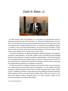
3 STRESS AND STRAINP rincipal StressesFor the special case of a two-dimensional stress state, the equations for principal stress reduce to,220abxyxyxyc22!=+-+=vvvvvvxvdnThe two nonzero values calculated from this equation are temporarily labeled a and b and the third value c is always zero in this case. Depending on their values, the three roots are then labeled according to the convention:algebraically largest = 1, algebraically smallest = 3, other = 2. A typical 2D stress element is shown below with all indicated components shown in their positive sense. Mohr's Circle Stress, 2 DTo construct a Mohr's circle, the following sign conventions are Tensile normal stress components are plotted on the horizontal axis and are considered positive. Compressive normal stress components are For constructing Mohr's circle only, shearing stresses are plotted above the normal stress axis when the pair of shearing stresses, acting on opposite and parallel faces of an element, forms a clockwise couple.
4 Shearing stresses are plotted below the normal axis when the shear stresses form a counterclockwise circle drawn with the center on the normal stress (horizontal) axis with center, C, and radius, R, where,CR22xyxyxy22=+=-+vvvvxdnThe two nonzero principal stresses are then: a = C + R b = C RThe maximum inplane shear stress is in = R. However, the maximum shear stress considering three dimensions is always .2max13=-xvvHooke's LawThree-dimensional case: x = (1/E)[ x v( y+ z)] xy = xy /G y = (1/E)[ y v( z+ x)] yz = yz /G z = (1/E)[ z v( x+ y)] zx = zx /GPlane stress case ( z = 0): x = (1/E)( x v y) y = (1/E)( y v x) z = (1/E)(v x + v y)Uniaxial case ( y = z = 0): x = E x or = E , where x, y, z = normal strain x, y, z = normal stress xy, yz, zx = shear strain xy, yz, zx = shear stressE = modulus of elasticityG = shear modulusv = Poisson's ratio Crandall, , and Dahl, An Introduction to MECHANICS of Solids, McGraw-Hill, New York, 1959.
5 ,in,RcwccwbyxyRC2axyxvEvvv110100021xyxyx yxy2=--vvxffcRTSSSSVXWWWW**44 78 MECHANICS OF MATERIALSTORSIONT orsion stress in circular solid or thick-walled (t > r) shafts:JTr=xwhere J = polar moment of inertiaTORSIONAL STRAIN limit//rzrddz0zz==czzDD"zD^^hhThe shear strain varies in direct proportion to the radius, from zero strain at the center to the greatest strain at the outside of the shaft. d /dz is the twist per unit length or the rate of ,GGrddzTGddzrdAGJddzGJTdzGJTL wherezzAoL2======xczzzzzz^^^hhh## = total angle (radians) of twistT = torqueL = length of shaftT/ gives the twisting moment per radian of twist. This is called the torsional stiffness and is often denoted by the symbol k or Hollow, Thin-Walled Shafts,AtT2wherem=xt = thickness of shaft wallAm = the total mean area enclosed by the shaft measured to the midpoint of the Force and Bending Moment Sign Conventions1. The bending moment is positive if it produces bending of the beam concave upward (compression in top fibers and tension in bottom fibers).
6 2. The shearing force is positive if the right portion of the beam tends to shear downward with respect to the left. The relationship between the load (w), shear (V), and moment (M) equations are:wxdxdVxVdxdMxVVwxdxMMVxdxxxxx2121121 2=-=-=--=^^^^^hhhhh7A##Stresses in BeamsThe normal stress in a beam due to bending: x = My/I, whereM = the moment at the sectionI = the moment of inertia of the cross sectiony = the distance from the neutral axis to the fiber location above or below the neutral axisThe maximum normal stresses in a beam due to bending: x = Mc/I, wherec = distance from the neutral axis to the outermost fiber of a symmetrical beam section. x = M/s, wheres = I/c: the elastic section modulus of the shear stress: xy = VQ/(Ib), whereV = shear forceQ = Ayll, whereA = area above the layer (or plane) upon which the desired transverse shear stress actsyl = distance from neutral axis to area centroidB = width or thickness or the cross-sectionTransverse shear flow:q = VQ/I Timoshenko, S.
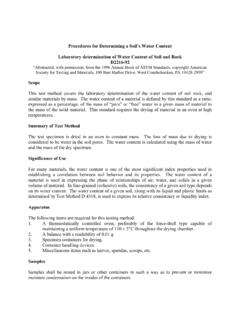
7 , and Gleason H. MacCullough, Elements of Strengths of MATERIALS , K. Van Nostrand Publishing Co., BENDINGNEGATIVE BENDINGNEGATIVE SHEARPOSITIVE SHEAR 79 MECHANICS OF MATERIALSD eflection of BeamsUsing 1/ = M/(EI),,//EIdxdyMEIdxdydMxdxVEIdxdydVxdx wdifferentialequationofdeflectioncurve22 34=====-43^^hhDetermine the deflection curve equation by double integration (apply boundary conditions applicable to the deflection and/or slope).EI (dy/dx) = M(x) dxEIy = [ M(x) dx] dxThe constants of integration can be determined from the physical geometry of the SectionsThe bending stresses in a beam composed of dissimilar MATERIALS (material 1 and material 2) where E1 > E2 are: 1 = nMy/IT 2 = My/IT , whereIT = the moment of intertia of the transformed sectionn = the modular ratio E1/E2E1 = elastic modulus of material 1E2 = elastic modulus of material 2 The composite section is transformed into a section composed of a single material.
8 The centroid and then the moment of inertia are found on the transformed section for use in the bending stress 1 MATERIAL 2E1, A1E2, A2bE2, A2E2, nA1 TRANSFORMEDSECTIONbnbNEUTRALAXISCOLUMNSC ritical axial load for long column subject to buckling:Euler's Formula,PKEI wherecr22,r=_i, = unbraced column lengthK = effective-length factor to account for end supportsTheoretical effective-length factors for columns include:Pinned-pinned, K = , K = , K = , K = buckling stress for long columns:/,APKrEwherecrcr22,vr==^hr = radius of gyration /IA/Kr, = effective slenderness ratio for the columnELASTIC STRAIN ENERGYIf the strain remains within the elastic limit, the work done during deflection (extension) of a member will be transformed into potential energy and can be the final load is P and the corresponding elongation of a tension member is , then the total energy U stored is equal to the work W done during = W = P /2 The strain energy per unit volume isu = U/AL = 2/2E (for tension) 80 MECHANICS OF MATERIALSMATERIAL PROPERTIEST able 1 - Typical Material Properties(Use these values if the specific alloy and temper are not listed on Table 2 below)SteelAluminumCast IronWood (Fir)BrassCopperBronzeMagnesiumGlassPoly styrenePolyvinyl Chloride (PVC)Alumina FiberAramide FiberBoron FiberBeryllium FiberBeO FiberCarbon FiberSilicon Carbide FiberMaterialModulus of Elasticity, E[Mpsi (GPa)] ( ) ( ) ( ) ( )
9 (102 125)17 (117) (96 120) (45) (70) (2)< (<4)58 (400) (125)58 (400) (300)58 (400) (700)58 (400)Modulus of Rigity, G[Mpsi (GPa)] ( ) ( ) ( ) ( ) (40) (45) (45) ( ) Poisson's Ratio, Coefficient of ThermalExpansion, [10 6/ F (10 6/ C)] ( ) ( ) ( ) ( ) ( ) ( ) ( )14 (25) ( ) ( ) ( ) Density, [lb/in3 (Mg/m3)] ( ) ( ) ( ) ( ) ( ) ( ) ( ) ( ) ( ) ( ) ( ) ( ) ( ) ( ) ( ) ( ) ( )Table 2 - Average Mechanical Properties of Typical Engineering MATERIALS ( Customary Units)(Use these values for the specific alloys and temperature listed. For all other MATERIALS refer to Table 1 above.)MaterialsMetallicAluminumWrought 22 Modulus ofElasticity EModulus ofRigidity GYield Strength (ksi)Ultimate Strength (ksi)% Elongation in2 in. specimenPoisson'sRatio vCoef. of y u(lb/in3)(103 ksi) (10 6)/ FNonmetallicConcreteTitaniumAlloyPlastic ReinforcedLow StrengthStructural A36 Gray ASTM 20 Malleable ASTM A-197 Red Brass C83400 Bronze C86100 SteelAlloysMagnesiumAlloyCopperAlloysCas t IronAlloys[ Ti-6Al-4V][ Am 1004-T611]Stainless 304 Tool L2 High StrengthKevlar 4930% GlassWoodGradeSelect StructuralDouglas FirWhite SpruceSPECIFIC VALUES MAY VARY FOR A PARTICULAR MATERIAL DUE TO ALLOY OR MINERAL COMPOSITION, MECHANICAL WORKING OF THE SPECIMEN, OR HEAT TREATMENT.
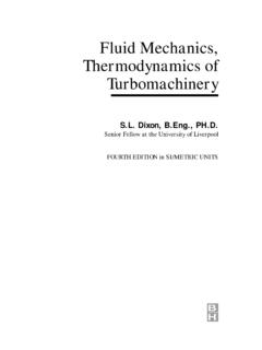
10 FOR A MORE EXACT VALUE REFERENCEBOOKS FOR THE MATERIAL SHOULD BE YIELD AND ULTIMATE STRENGTHS FOR DUCTILE MATERIALS CAN BE ASSUMED EQUAL FOR BOTH TENSION AND PERPENDICULAR TO THE PARALLEL TO THE MEASURED PERPENDICULAR TO THE GRAIN WHEN THE LOAD IS APPLIED ALONG THE GRAIN.(103 ksi) Hibbeler, , MECHANICS of MATERIALS , 4th ed., Prentice Hall, 2000. 81 MECHANICS OF MATERIALSPP vmaxmaxmaxmaxmaxxMPab(L+a)6 EIL6 EIL243EI6 EIL6 EIL(L2 b2 a2)22(L2 b2 x2)(3L2 4x2) Pab(L+b) Pba Pbx PxvLEIM00M L016EI48EI48EI0 x L/20 x aL36EI6 EIL24EI384EI768EI x < L x03848x3 24Lx2(3x4 10L2x2 + 7L4)+ 17L2x L3)38416x3 24Lx2 + 9L3) wx wxx=amaxvmaxvmaxvat xvvvvmaxvvw=======M L0 ===================PL2 PL312L2L2 Simply Supported Beam Slopes and DeflectionsBEAMSLOPEDEFLECTIONELASTIC CURVE vvvvL21 1 1 max 1 2 2 2 2 1 1 2 21 232M x0 LLLL7wLxat 7w0L3w0L4w0L3360EI45EI3 3wLx3xxxLL2L3)3L22 ++ 345wLwL wL wEIEIEIEIEIL 44abvL(((()0 x L/2x = L/2 x Hibbeler, , MECHANICS of MATERIALS , 4th ed.