Transcription of Mechanisms of Heat Transfer - University of Oklahoma
1 heat TRANSFERM echanisms of heat Transfer :(1) Conductionwhere Qis the amount of heat , Btu, transferred in time t, hkis the thermal conductivity, Btu/[h ft2(oF/ft)]Ais the area of heat Transfer normal to heat flow, ft2 Tis the temperature, oFxis the thickness of the conduction path, ft.(2) Convectionhis the heat Transfer coefficient, Btu/[h ft2oF].dxdTAkdtdQ =TAhdtdQ =ChE 4253 - Design IChE 4253 - Design IHEAT TRANSFERM echanisms of heat Transfer :(3) Radiationwhere is the Stefan-Boltzmann constant = 10-8 Btu/(h ft2oR4) is the emissivity of surfaceAis the exposed area for heat Transfer , ft2 Tis absolute temperature, =ChE 4253 - Design IChE 4253 - Design IOverall heat Transfer CoefficientDefinition of the overall heat Transfer coefficient, UU[=] Btu/(h ft2oF) Ttotis the total temperature difference (overall driving force for the process).
2 Important:The overall heat Transfer coefficient, U, is an approximate is defined in combination with the area A ( inside/outside area of a pipe).totTAUq =ChE 4253 - Design IChE 4253 - Design IGeneral correlation:Intensity=Potential/Resistan ceRate = Driving Force/ResistanceApplies for electricity, flow, flux transport: Overall resistance, R=1/UAOverall heat Transfer CoefficienttotTAUq =rinroutHeat fluxChE 4253 - Design IChE 4253 - Design IResistances in series:Overall resistance = Sum of resistancesIn our case:Uo: overall heat Transfer coefficient based on the outside areaho, hi: outside/inside film heat Transfer coefficient do, di: outside/inside pipe diameterkw: wall thermal conductivityhod, hid: outside/inside fouling heat Transfer coefficientOverall heat Transfer CoefficientrinroutHeat flux()idioiiowiooodoohddhddkdddhhU112ln1 11++++=ChE 4253 - Design IChE 4253 - Design IHeat Transfer EquipmentUsual terminology: exchanger .
3 heat exchange between two process streams. Heater or Cooler: a process stream is heated/cooled by a utility stream. Vaporiser: a process stream is completely vaporised. Reboiler: vaporiser associated with a distillation column. Evaporator: used to concentrate a solution. Fired heater: heating is done by 4253 - Design IChE 4253 - Design IHeat Transfer Equipment Double-pipe exchanger , used for cooling or heating. Shell and tube heat exchangers Plate-fin exchangers. Spiral heat exchangers. Air cooled: coolers and condensers. Fired 4253 - Design IChE 4253 - Design IHeat Transfer EquipmentTube and shell heat exchanger :ChE 4253 - Design IChE 4253 - Design IHeat Transfer EquipmentTube and shell heat exchanger :ChE 4253 - Design IChE 4253 - Design IHeat Transfer EquipmentTube and shell heat exchanger :ChE 4253 - Design IChE 4253 - Design IHeat Transfer EquipmentTube and shell heat exchanger :ChE 4253 - Design IChE 4253 - Design IChE 4253 - Design IChE 4253 - Design IHeat Transfer EquipmentTube and shell heat exchanger : BafflesChE 4253 - Design IChE 4253 - Design IHeat Transfer EquipmentTube and shell heat exchanger .
4 Tube PitchChE 4253 - Design IChE 4253 - Design IHeat Transfer EquipmentTrainsChE 4253 - Design IChE 4253 - Design IHeat Transfer EquipmentTEMAT ubular ExchangerManufacturers AssociationChE 4253 - Design IChE 4253 - Design IHeat Transfer EquipmentSpiral ExchangersHeat Transfer EquipmentPlate ExchangersChE 4253 - Design IChE 4253 - Design IChE 4253 - Design IChE 4253 - Design IHeat Transfer EquipmentSpiral Wound ExchangersChE 4253 - Design IChE 4253 - Design IHeat Transfer EquipmentAir CoolersChE 4253 - Design IChE 4253 - Design IHeat Transfer EquipmentLNG ExchangersPlate Special Shell and Tube heat Exchangers - Typical Old Fashion design1) Define duty: heat Transfer rate, flows, ) Collect required physical properties ( , , k).3) Decide on the type of ) Select a trial value for ) Calculate the mean temperature difference, Tm6) Calculate area ) Decide on the exchanger ) Calculate individual ) Calculate U.
5 If significant difference from step (4), substitute in (4) and ) Calculate the pressure drop. If it is not satisfactory, back to (7) or (4) or (3).11) Optimise: repeat (4) to (10) to determine cheapest solution (usually smaller area). ChE 4253 - Design IChE 4253 - Design INow we have:at every location in the exchanger . In differential form:and in a simplified integral/overall form (used in step 6) : heat Exchangers(4) Use first order approximations for U, such as table 14-5 pg. 663 in PT& =()()dATUdqloctotloc =mTAUq =ChE 4253 - Design IChE 4253 - Design IOverall heat Transfer CoefficientChE 4253 - Design IChE 4253 - Design I(5) Mean temperature difference for counter-current flow:In reality, combination of co-current, countercurrent and cross flow. What do we do? Use a correction factor, Ft, (see figs 14-4 and 14-5 in PT&W)Parameters: heat ExchangersT1T2t2t1()()()()12211221lntTtT tTtTTTlmm = = lmtmTFT = ()()()()11121221,tTttSttTTR = =ChE 4253 - Design IChE 4253 - Design IHeat Transfer EquipmentCorrection factor: heat Transfer EquipmentCorrection factor: heat Transfer EquipmentCorrection factor: heat Transfer EquipmentCorrection factor: heat Exchangers - Typical design1) Define duty: heat Transfer rate, flows, ) Collect required physical properties ( , , k).
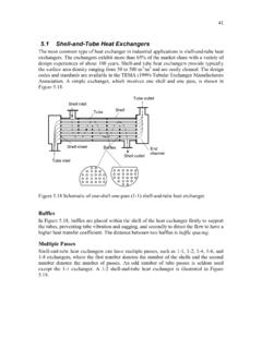
6 3) Decide on the type of ) Select a trial value for ) Calculate the mean temperature difference, Tm6) Calculate area ) Decide on the exchanger ) Calculate individual ) Calculate U. If significant difference from step (4), substitute in (4) and ) Calculate the pressure drop. If it is not satisfactory, back to (7) or (4) or (3).11) Optimise: repeat (4) to (10) to determine cheapest solution (usually smaller area). ChE 4253 - Design IChE 4253 - Design IShell and Tube heat ExchangersMost commonly used heat : Large surface area in a small volume. Good mechanical layout. Uses well established fabrication methods. Can be constructed from a wide variety of materials. Easily cleaned and maintained. Well established design 4253 - Design IChE 4253 - Design IShell and Tube heat ExchangersTube size:Length is standard, commonly 8, 12 or 16 : most common 3/4 or 1 in OD Tube pitch and clearance:Pitch is the shortest center-to-center distance between adjacent tubes.
7 Commonly to time the tube is the distance between tubes. It should be larger than 25% of the tube or square arrangement of tubes are quite common. Baffles:Baffles are usually spaced between 20% and 100% of the ID of the 4253 - Design IChE 4253 - Design IShell and Tube heat ExchangersFluid location:Corrosive fluids flow inside the with higher fouling tendency inside the pressure fluid inside the tubes (if everything else the same). Hot fluid inside the velocities: Liquids: 1-2 m/s in tubes, max 4 m/s to reduce to 1 m/s in shellVapors: 50-70 m/s (vacuum), 10-30 m/s (1 bar), 5-10 m/s (high P)ChE 4253 - Design IChE 4253 - Design IShell and Tube heat ExchangersShell:Up to 24 in nominal size, use standard : Most usual pass is one (type E according to TEMA standards). Split flow arrangement (types G and J) are used for pressure drop reduction, when the pressure drop is the controlling factor in the 4253 - Design IChE 4253 - Design ISingle phase streams with constant Cpand no pressure effect on enthalpy:Pure components undergoing phase change: heat Exchangers: The T-Q Diagram A T-Q diagram is a visual representation of the energy balance equation for each =& mq&=200oC100oC400oC175oCChE 4253 - Design IChE 4253 - Design IThe T-Q diagram reveals two important truths regarding heattransfer:(1) T-lines for counter-current flows do not cross!
8 It is impossible.(2) T-lines should not approach each other too closely: As they approach, the area required for heat Transfer goes to point of closest approach is called pinch Exchangers: The T-Q DiagramFor the previous example:400oC200oC100oC175oCDriving ForceSlope=1/m2Cp2 Slope=1/m1Cp1 TQChE 4253 - Design IChE 4253 - Design I(a)A single-phase stream is heated from 100 to 200oC by condensing saturated steam to saturated liquid at 250oCin a countercurrent heat exchanger .(b)A single-phase stream is heated from 120 to 220oC by condensation of saturated steam at 250oC and by subcooling the liquid to 225oC in a countercurrent heat Exchangers: The T-Q DiagramExamples:(a)(b)250oC100oC200oCTQ2 50oC250oC120oC220oCTQ225oCCondensingzone subcoolingzoneChE 4253 - Design IChE 4253 - Design IShell and Tube heat Exchangers - Design Tube side: Configuration (pitch, number of tubes, dimensions).
9 heat Transfer drop. Shell side: Configuration (dimensions, baffles). heat Transfer influenced by: heat Transfer area Tube diameter and length Pressure Material of construction Baffle type Special features, such as U bends, floating heads, fins 4253 - Design IChE 4253 - Design ITube Side1) Define duty: heat Transfer rate, flows, ) Collect required physical properties ( , , k).3) Select a value for ) Calculate the mean temperature difference, Tm. Use the correction factor, Ft .6) Calculate area ) Decide on the exchanger one of the standard tube lengths and tube diameters. Calculate the number of tubes needed from the area estimated in (6). Decide on bundle diameter from the following:11nobtdDKN =111ntobKNdD =ChE 4253 - Design IChE 4253 - Design ITube SideNtis the number of tubesDbis the bundle diameterdois the tube outside diameterConstants:Triangular pitch, pt= passes12468K1 pitch, pt= passes12468K1 =ChE 4253 - Design IChE 4253 - Design IHeat Transfer EquipmentTube SideFrom the bundle diameter calculate shell diameter!
10 8) Calculate heat Transfer turbulent flow inside the tubes (Sieder & Tate):Nuis the Nusselt number, Nu = hide / kfReis the Reynolds number, Re= ut de /mPris the Prandtl number, Pr = Cp / kfutis the fluid velocity inside the tube,kf is the fluid conductivityde is the equivalent (hydraulic) diameterde = 4 x (cross section area available to flow)/(heated perimeter)C= for gases, for non-viscous and for viscous =wCNu ChE 4253 - Design IChE 4253 - Design ITube SideUse of the heat Transfer factor, jh,for transition and laminar flow:See figure 14-9 in page 658 of PT& , see table 14-3, pg. 661 in PT& ) Calculate pressure the friction factor, as for pipe flows, in the Fanning =whjNu ChE 4253 - Design IChE 4253 - Design IHeat Transfer FactorChE 4253 - Design IChE 4253 - Design ITube Side9) Calculate pressure the friction factor for isothermal flow at the mean temperature npis the number of tube passesgcis the unit conversion factor iis a correction factor for non-isothermal flowfor Re < 2100for Re > 2100 Biis a correction factor for friction due to contraction, expansion and reversal of flow directionGis the mass velocity inside the tubeiiicpiiidgLnGfBP 22= () =() =ChE 4253 - Design IChE 4253 - Design IShell SideFrom the bundle diameter we have the shell diameter (step 7)!