Transcription of MELBOURNE RETAIL WATER AGENCIES - MRWA
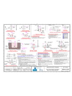
1 1 2 3 4 5 6 7 8 9 10 11 12. FSL Fit and tape in place a full circumferential Restrained pipeline. E. - TRENCH TRENCH oversized plastic pipe sleeve, extending > 150. Use any of Options B or > 2m C from MRWA-W-104A. EDGE Restrained pipeline. EDGE past both sides of the restraint. A Use any of Options B or A. C from MRWA-W-104A. THRUST. 50 25 MESH RESTRAINT. POSSIBLE GAS MAIN MIN 300 MIN 300. ALIGNMENT TIE WIRE AREA (A 1). MAY. EXTEND INTO. B MIN 150 DRAINAGE. - Connect both MAX 300 TRENCH. mains to inline THRUST. thrust restraint via restrained mains RESTRAINT. D AREA (A 1) NDW DW COMPACTED. - GAS. B 75 25 FCR B. >150. POSSIBLE GAS MAIN. ALIGNMENT Min 150 for mains > DN150. Zero OK for mains <-DN150. TRENCH TRENCH. EDGE EDGE THRUST RESTRAINT AREA PUDDLE FLANGES ON VALVED DRAIN. FIGURE 205B-C: PLAN VIEW.
2 TEE CROSSING WITH AREA UNDER. A = 2A 1 + A 2 = SHADED AREA MAINS REFER MRWA-W-306 A & B. FIGURE 205B-A: PLAN VIEW. TEE CROSSING WITH DOGLEG BENDS & INLINE RESTRAINT TRENCH (A 2). HOST MAINS AT DIFFERENT DEPTHS FIGURE 205B-E: ELEVATION. DUAL WATER IN LINE. Restrained pipeline. Gas main and trench edge Use any of Options B or if NDW main drops under Gas main and trench CONCRETE THRUST RESTRAINT. C from MRWA-W-104A. edge if DW main is lower C Trench edge if DW C. > 2m main drops under Gas main and NOTES on Steel Reinforcing: Puddle flange. trench edge if NDW a. Inline thrust restraint reinforcement is to consist of mesh as per Trench edge if NDW. Refer MRWA-W-306 main is lower main drops under TABLE 205B-A: IN LINE RESTRAINT STEEL Table 205B-A and N10 grade bar (as per AS/NZS 4671). Connect both b.
3 Steel reinforcement shall have 75 clear cover of concrete ( 25). mains to inline REINFORCEMENT SELECTION (DUAL MAINs). thrust restraint via c. Where there are 2 layers of reinforcement, maintain min 150. THRUST RESTRAINT AREA MESH REQUIREMENTS separation between layers. restrained mains 1 Layer of SL81 d. Cut reinforcement or tie in additional bars to ensure to 1 Layer of RL1018 or 2 layers of SL81 reinforcement is located within 50 25 of pipe OD at all to m 2 layers of SL81 intersections of reinforcement and pipe. D > 2 layers of RL1018 e. When using RL (rectangular mesh) in longitudinal restraints, the D. Gas main if DW main drops under. main wire (thicker & closer spaced wire) shall span the trench. THRUST. Trench edge if gas main in this location not RESTRAINT AREA shown for clarity. FIGURE 205B-D: SECTION VIEW.
4 TEE CROSSING. FIGURE 205B-B: SECTION VIEW. TEE CROSSING WITH DOGLEG BENDS & INLINE RESTRAINT WITH HOST MAINS AT DIFFERENT DEPTHS. GENERAL NOTES: 1. Cast the thrust area of all thrust restraints against a clean 5. All concrete restraints must be formed at the sides (ie: NOTES Regarding Plain Restraints: NOTES Regarding Inline Thrust Restraints: face of a material with an AHBP > 50 kPa. edges other than bearing surface) using temporary A. Any restrained pipework can be used between the thrust restraint and the Tee (ie: Key References: formwork or sand bags. Plain thrust restraints shall have a minimum of 2m of solid Where soils have an AHBP < 50 kPa, restrained joints any of Options B or C from MRWA-W-104A). a. Refer to MRWA-W-200 for soil classifications details. 7. When pouring concrete against fittings place a membrane undisturbed ground behind the bearing area.
5 Shall instead be used as per MRWA-W-207. If PE is used, a restraint is not required at the 'Tee' end (If CWW or YVW). b. Refer to MRWA-W-201 & 202 for trench, of polyethylene, PVC or felt between the fitting and E For plain restraints, maximum encasement around pipe to be 180 . Do not cast thrust restraints against loose sand or landfill. E. If PE is used, the in line restraint shall take into account shrinkage forces (Refer embedment and backfill details. concrete to prevent damage to the fitting. All dual main plain concrete restraints must be steel reinforced with 2. Thrust restraints shall not interfere with other services. Figure-205A-L). c. Refer to MRWA-W-202 for horizontal and vertical Joints, bolts and nuts to be clear of concrete. SL81 mesh. Restraints maybe cast around sleeved gas services (as B.)
6 In line thrust restraints shall have a minimum of 2m of solid undisturbed ground or clearances between mains. 8. For dual WATER restraints, the required bearing area is to Minimum cover of all mains shall be met when mains are at shown) where there is no reasonable alternative. compacted crushed rock around the bearing area on both sides of the restraint. d. Refer to MRWA-W-204 for thrust area requirements. be the addition of the required area for each pipe (ie: differing depths. 3. Gas mains shall be deflected away from the concrete C. For Reducers, it is acceptable to place an in line concrete restraint behind the pipe e. Refer to MRWA-W-104B for details on dual WATER assume both valves closed). For information on Vertical Deflection of mains, refer to restraint where practicable and minimum cover can be socket instead of around a puddle flange.
7 Opposing bend & tee arrangements. 9. Shared Trenches shall not exceed 3 pipelines or have MRWA-104B & 212. maintained above the gas main. D. The outer tee may be restrained with a plain restraint instead of an in line restraint. f. Refer MRWA-W-306A & B for puddle flange details. any mains > DN250 without WATER agency approval. Higher main (whether DW or NDW) shall be the one closest to the 4. Use grade N20 concrete or better. bearing surface. Gas main if NDW Gas main if Gas main if NDW Gas main if DW. F main nearest Gas main if DW NDW main F. Gas main if DW main nearest main nearest J 250. bearing surface main nearest nearest main nearest bearing surface bearing surface - MIN. 250 MIN bearing surface bearing bearing surface 250 MIN. surface BEARING SURFACE. H > 100 > 100. - Trench profile adjacent to Top pipe thrust restraints, unless trench restraint area > 100.
8 BEARING. has flat trench floor as G AREA. per Fig 202-D. - 75 25. G G. Bottom pipe STEEL. thrust STEEL. REINFORCING REINFORCING 75 25. restraint area 75 25. MESH. FIGURE 205B-F: PLAN VIEW. FIGURE 205B-G: SECTION VIEW. FIGURE 205B-H: SECTION VIEW. FIGURE 205B-I: PLAN VIEW. FIGURE 205B-J: SECTION VIEW. DUAL WATER TEE PLAIN THRUST RESTRAINT LOWER TEE PLAIN THRUST RESTRAINT UPPER TEE PLAIN THRUST RESTRAINT DUAL WATER PLAIN BEND RESTRAINT DUAL WATER PLAIN BEND RESTRAINT. MELBOURNE RETAIL WATER AGENCIES . DESIGNED: R. JAGGER DATE: 20/01/2011 MRWA WATER SUPPLY STANDARDS NOT TO SCALE. DRAWN: R. JAGGER DATE: 20/01/2011. H H. 3 ALTERED STEEL REINFORCEMENT 01/12/16 RJ / CP / JT CHECKED: NAME DATE APPROVED: NAME DATE. 2. 1. PUBLISHED FIRST ISSUE. PRE PUBLISHED DRAFT FOR COMMENT. 23/03/12 R. JAGGER. 12/07/11 R.
9 JAGGER. X CWW. X SEWL. C. RIVETTE. 23/03/12. 23/03/12. X CWW. X SEWL. 23/03/12. 23/03/12. DUAL MAIN CONCRETE RESTRAINTS MRWA-W-205B. REV DESCRIPTION DATE APPROVED X YVW 23/03/12 X YVW 23/03/12 ISSUED 2016 REVISION NO. 3. 1 2 3 4 5 6 7 8 9 10 11 12.