Transcription of Metal Framing Channels - Cooper Industries
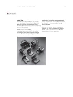
1 ChannelMetal Framing channel is cold formed on our modern rolling mills from 12 Ga. ( ), 14 Ga. ( ), and 16 Ga. ( )lowcarbon steel strips. A continuous slot with inturned lips provides the ability to make attachments at any & TolerancesAll Channels excluding SH style 1/8 ( )on 10 ( )and 3/16 ( )on 20 ( )All SH Channels only 1/4 ( )on 10 ( )and 1/2 ( )on 20 ( )Custom lengths are available upon series of Channels offer full flexibility. A variety of pre-punched slot patterns eliminate the need for precise fieldmeasuring for hole locations. Slots offer wide adjustments in the alignment and bolt variety of pre-punched 9/16 ( mm)diameter hole patterns are available in our Channels . These hole patterns provide aneconomical alternative to costly field drilling required for many used with series B217-20 Closure Strips, knockout Channels can be used to provide an economical listed surfaceraceway.
2 Channels are furnished with 7/8 ( mm)knockouts on 6 (152 mm)centers, allowing for perfect fixture alignment onspans up to 20 ( m).Materials & Finishes (Unless otherwise noted)Steel: Plain & Pre-galvanized12 Ga. ( ), 14 Ga. ( )and 16 Ga. ( )Note: A minimum order may apply onspecial material and Load (Steel & Stainless Steel)The design loads given for strut beam loads are based on a simple beam condition using an allowable stress of 25,000 psi. This allowable stress results in a safety factor of This is based upon virgin steel minimum yield strength of 33,000 psi cold worked during rolling to an average yieldstress of 42,000 psi. For aluminum channel loading multiply steel loading by a factor of spacing is maintained between 21/2inches ( mm)and 4 inches ( mm)on center. Through high quality controltesting of welded Channels and continuous monitoring of welding equipment, we provide the most consistent combinationchannels available dimensions are shown in parentheses.
3 Unless noted, all metric dimensions are in A1011, 33,000 PSImin. yieldGRNDURA GREEN GLVPre-GalvanizedASTM A653 33,000 PSImin. yieldHDGHot-Dipped GalvanizedASTM A123 YZNY ellow Zinc ChromateASTM B633 SC3 Type IISS4 Stainless Steel Type 304 ASTM A240SS6 Stainless Steel Type 316 ASTM A240 ALAluminumAluminum 6063-T6 Channel & CombinationsMetal Framing ChannelsStrut Systems15 ChannelMaterial & Thickness *Channel Hole Pattern **DimensionsStainlessSHSH17/8TH KO6 SteelChannelHeightWidthTypeSteel Alum. Type Type304 3161234B1131/4 ( )15/8 ( )12 Ga..105 111 1B1227/16 ( )15/8 ( )12 Ga..105 12112 12B2215/8 ( )15/8 ( )12 Ga..105 12 Ga. 12 ( )15/8 ( )14 Ga..080 14 Ga. 14 12B2615/8 ( )15/8 ( )16 Ga. 111 1B3213/8 ( )15/8 ( )12 Ga. 12 Ga. 13113 1B421 ( )15/8 ( )12 Ga. 12 Ga. 13113 1B5213/16 ( )15/8 ( )12 Ga. 12 Ga. 12 1B5413/16 ( )15/8 ( )14 Ga.
4 080 14 Ga. 14 12B5613/16 ( )15/8 ( )16 Ga. 111 1B6213/16 ( )13/16 ( )18 Ga. B7213/32 ( )13/16 ( )18 Ga. Selection Chartfor Channels , Materials and Hole PatternsThe selection has been prepared to provide a reference for available channel, materials and hole patterns. Material typesavailable for various hole patterns are defined by numbers 1thru stainless steel Channels with hole patterns are available on special order only.*Metric equivalent for thicknesses shown in chart.**1- Steel12 Ga. = mm18 Ga. = mm2- Aluminum14 Ga. = = mm3- Type 304 Stainless Steel16 Ga. = = mm4- Type 316 Stainless SteelProperties may vary due to commercial tolerances of the Part NumberingExample:B22SH- 120SS4 Channel Type Hole Patterns Length Material/FinishB11SH (pg. 40)120 GRNB12S (pg. 40)240 GLVB22 H178 (pg.)
5 40)HDGB24 TH (pg. 41)YZNB26K06 (pg. 41)SS4B32 SHA (pg. 41)SS6B42S58 (pg. 42)ALB52 M (pg. 42)B54 H25 (pg. 43)B56H112 (pg. 42)B62* Leave blank for no hole patternB729/16 x11/8 slots on 2 centers13/32 x 3 slots 9/16 diameterholes9/16 diameteron 17/8 centers7/8 diameterknockoutsReference page 15 for general fitting and standard finish & CombinationsChannel16 Strut SystemsB11 Thickness: 12 Gauge ( mm) Standard lengths: 10 ( m)& 20 ( m) Standard finishes: Plain, DURA GREEN ,Pre-Galvanized, Hot-Dipped Galvanized,Aluminum Weight: ( kg/m)15/8 ( )31/4 ( )13/16 ( ) ( )3/8 ( )3/8 ( )9/32 ( )7/8 ( )XYYXR eference page 15 for general fitting and standard finish & CombinationsBeam LoadingBased on simple beam condition using an allowable design stress of 25,000 psi (172 MPa)in accordance with MFMA, with adequate lateralbracing (see page 12 for further explanation).
6 Actual yield point of cold rolled steel is 42,000 psi (289 MPa). To determine concentrated loadcapacity at mid span, multiply uniform load by and corresponding deflection by *Failure determined by weld Channel, Combinations & Load DataStrut Systems17 Areas of Momentof Section Radius of Moment of Section Radius ofChannel WeightSection Inertia (I) Modulus (S) Gyration (r) Inertia (I) Modulus (S) Gyration (r) kg/m sq. in. ( ).900( ) ( ).6472( ) ( ).4357( ).5362( ).696 ( ) ( ) ( ) ( ) ( ) ( ).8714( ) ( ).696( )X - X Axis Y - Y AxisCalculations of section properties are based on Metal thicknesses as determined by the AISI Cold-Formed Steel Design PropertiesUniform Load @ Deflection =Beam SpanChannelUniform Load and Deflection1/240 Span 1/360 SpanIn. (609)B115130( ).029(.73)5130( )5130( )B11A5130*( ).005(.13)5130*( )5130*( )36(914)B113488( ).
7 065( )3488( )3488( )B11A5130*( ).017(.43)5130*( )5130*( )48(1219)B112616( ).117( )2616( )2616( )B11A5130*( ).040( )5130*( )5130*( )60(1524)B112093( ).183( )2093( )1908( )B11A5130*( ).079( )5130*( )5130*( )72(1829)B111744( ).263( )1744( )1325( )B11A5130*( ).136( )5130*( )5130*( )84(2133)B111495( ).358( )1460( )974( )B11A4552( ).191( )4552( )4552( )96(2438)B111308( ).468( )1118( )745( )B11A3983( ).250( )3983( )3983( )108(2743)B111163( ).592( )884( )589( )B11A3541( ).317( )3541( )3353( )120(3048)B111046( ).731( )716( )477( )B11A3187( ).391( )3187( )2716( )144(3657)B11872( ) ( )497( )331( )B11A2656( ).563( )2656( )1886( )168(4267)B11747( ) ( )365( )243( )B11A2276( ).766( )2078( )1386( )192(4877)B11654( ) ( )280( )186( )B11A1992( ) ( )1591( )1061( )216(5486)B11581( ) ( )221( )147( )B11A1770( ) ( )1257( )838( )240(6096)B11523( ) ( )179( )119( )B11A1593( ) ( )1018( )679( )Note:Aluminum loading, for B11, can be determinedby multiplying load data times a factor of Loading**Where the slenderness ratio KLexceeds 200, and K = end fixity factor, L = actual length and r = radius of page 15 for general fitting and standard finish & Combinations31/4 ( )61/2 ( )31/4 ( )15/8 ( )31/4 ( ) ( )15/8 ( )13/16 ( )XXYYYXXYB11 AWt.
8 ( kg/m)B11 BWt. ( kg/m)B11 Beam & Column Loading Data18 Strut SystemsMax. Column Loading K = .80 Max. Column Loading (Loaded @ )UnbracedChannelLoaded@ FaceK = .65K = K = mmLbs. kNLbs. kNLbs. kNLbs. kNLbs. kN24(609)B118190( )4477( )8446( )7783( )7311( )B11A17701( )8267( )17778( )17572( )17416( )36(914)B117311( )4183( )7838( )6503( )5612( )B11A17416( )8189( )17590( )17127( )16774( )48(1219)B116214( )3783( )7053( )4988( )3816( )B11A17016( )8079( )17327( )16503( )15876( )60(1524)B114988( )3279( )6140( )3595( )2790( )B11A16503( )7727( )16988( )15701( )14721( )72(1829)B113816( )2444( )5146( )2790( )2213( )B11A15876( )6160( )16574( )14721( )13310( )84(2133)B113063( )1897( )4133( )2291( )1846( )B11A15135( )4961( )16084( )13563( )11642( )96(2438)B112564( )1532( )3398( )1953( )1591( )B11A14279( )4045( )15520( )12226( )9717( )108(2743)B112213( )1273( )2886( )1708( )1401( )B11A13310( )3337( )14880( )10712( )7725( )120(3048)B111953( )1081( )2514( )1522( )1251**( )B11A12226( )2784( )14164( )9019( )6257**( )144(3657)B111591( )816( )2011( )1251**( )1026**( )B11A9717( )1990( )
9 12508( )6257**( )4345**( )168(4267)B111347( )642( )1687( )1058**( )859**( )B11A7183( )1464( )10550( )4597**( )3192**( )192(4877)B111167**( )519( )1459( )910**( ) B11A5499**( )1121( )8330( )3520**( ) 216(5486)B111026**( )429( )1285**( ) B11A4345**( )885( )6582**( ) 240(6096)B11910**( )360( )1148**( ) B11A3520**( )717( )5331**( ) B12 Thickness: 12 Gauge ( mm) Standard lengths: 10 ( m)& 20 ( m) Standard finishes: Plain, DURA GREEN , Pre-Galvanized,Hot-Dipped Galvanized, Aluminum Weight: ( kg/m)15/8 ( )27/16 ( )27/16 ( )47/8 ( )31/4 ( )15/8 ( )27/16 ( ) ( )15/8 ( )13/16 ( )13/16 ( ) ( )3/8 ( )3/8 ( )9/32 ( )XYYXXXYYYXXYB12 AWt. ( kg/m)B12 BWt. ( kg/m)Reference page 15 for general fitting and standard finish & Combinations7/8 ( )B12 Channel & CombinationsStrut Systems19 Areas of Momentof Section Radius of Moment of Section Radius ofChannel WeightSection Inertia (I) Modulus (S) Gyration (r) Inertia (I) Modulus (S) Gyration (r) kg/m sq.
10 In. ( ).731( ).5349( ).4061( ).856( ).3377( ).4156( ).680( ) ( ) ( ) ( ) ( ) ( ).6756( ).8315( ).680( )X - X Axis Y - Y AxisCalculations of section properties are based on Metal thicknesses as determined by the AISI Cold-Formed Steel Design PropertiesNote:Aluminum loading, for B12, can be determinedby multiplying load data times a factor of LoadingColumn LoadingBased on simple beam condition using an allowable design stress of 25,000 psi (172 MPa)in accordance with MFMA, with adequate lateralbracing (see page 12 for further explanation). Actual yield point of cold rolled steel is 42,000 psi. To determine concentrated load capacity atmid span, multiply uniform load by and corresponding deflection by *Failure determined by weld shear.**Where the slenderness ratio KLexceeds 200, and K = end fixity factor, L = actual length and r = radius of page 15 for general fitting and standard finish & CombinationsB12 Beam & Column Loading Data20 Strut SystemsUniform Load @ Deflection =Beam SpanChannelUniform Load and Deflection1/240 Span 1/360 SpanIn.