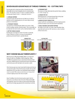
Transcription of METHOD OF ROLLING THREADS
1 Dec. 5, 1944. J. H. HOERN 2,364,442. METHOD OF ROLLING THREADS . Dec. 5, 1944. J. ?. ???RN 2,364442. METHOD OF ROLLING THREADS x Filed June 4, 1943. 2 Sheets-Sheet 2. ATTORNEYs. Patented Dec. 5, 1944 2,364,442. UNITED STATES PATENT OFFICE METHOD OF ROLLING HREADS. Joseph H. Hoern, Birmingham, Mich, assignor to Eaton Manufacturing Company, Cleveland, Ohio, a corporation of Ohio Application June 4, 1943, Serial No. 489,639. 13 Claimis. (C. 80-6). This invention relates to the ROLLING of screw dies is effected while the dies are so laterally Sep THREADS on machine parts such as bolts, screws arated from one another, and then the dies are and the like by means of flat dies and has for its caused to laterally approach each other to con principal obect the provision of a METHOD of roll plete the imbedding thereof in the work.
2 The pro ing THREADS in this manner by the practice of 5 vision of a METHOD as above described including which THREADS may be produced on a part as ac the step of initially locating the Workpiece cen Curately as has heretofore been possible by grind trally between the two relatively movable die ing operations. parts prior to gripping the workpiece between such Objects of the invention include the provision parts; and the provision of a METHOD of ROLLING of a METHOD of ROLLING screw THREADS on a part O THREADS as above described in Which the relative to be provided therewith by the practices of which movement of the die parts laterally With respect THREADS of an extremely accurate character may to each other is effected by the use of fluid pres be formed within extremely close tolerances; the Se.
3 Provision of a METHOD of ROLLING screw THREADS on Still further objects of the invention include the a part between flat dies by the practices of which 5 provision of a new and novel METHOD of checking the possibility of metal overlapping in the THREADS the position of one die part with respect to the of the work is effectively eliminated; the pro other to determine the accuracy of alignment Vision of a METHOD as above described in which between them; the provision of a METHOD of perfect alignment of the THREADS on the dies with checking the accuracy of alignment of flat thread respect to the THREADS being formed on the work 20 ROLLING dies with respect to each other including is assured at all times.
4 The provision of a METHOD the steps of initially effecting a partial imbedding as above described in which diametrical distor of the dies in the Work and then checking the tion of the body of the work under the force of alignment of the relatively shallow grooves thus the dies is effectively eliminated, and the provision formed in the work; and the provision of a meth 25 od as herein described in which the alignment of of a METHOD of ROLLING screw THREADS by fat dies in which the life of the dies is materially extend the relatively shallow grooves is checked by the ed as compared with those employed in conven use of an optical projector.
5 Tional methods . Additional objects of the invention include the Other objects of the invention include the pro provision of a METHOD of ROLLING THREADS between vision of a METHOD of ROLLING screw THREADS on 30 substantially fiat dies in which the dies are moved Workpieces by means of flat dies including the longitudinally relative to each other at a con steps of insuring initiation of the ROLLING move stant Speed whereby to result in better work and ment of the work between the dies when the dies longer life of the dies than in accordance with are in a
6 Predetermined position with respect to conventional methods ; and the provision of a each other in the direction of their movement 3 5 METHOD in which the speed of operation of the longitudinally with respect to each other, by first dies may be simply varied to enable the highest effecting only partial imbedding of the dies in the safe speed of operation to be maintained between Work and thereafter effecting a complete imbed the dies and the work commensurate with the ding of the dies in the work; the provision of a hardness of the Work and the practical life of the METHOD as above described in which the final 40 dies.
7 Imbedding of the dies in the work is accomplished The above being among the objects of the pres gradually; the provision of a METHOD as above ent invention, the same consists in certain novel described in which the final imbedding of the step or steps of operation to be hereinafter de dies in the work is accomplished by a bodily shift scribed with reference to the accompanying draw able movement of one of the dies laterally with 45 ings, and then claimed, having the above and respect to the other thereof; the provision of a other objects in view. METHOD as above described in which the dies are In the accompanying drawings which illustrate Separated from one another prior to the time the more or less diagrammatically apparatus by workpiece is discharged from between them; the means of which the METHOD of the present inven provision of a METHOD as above described in which i tion may be carried Out, and the association of.
8 The dies are initially separated from one another the work therewith, by a distance greater than that required to form Fig. 1 is a fragmentary, broken and partially complete THREADS on the work but less than the . sectioned plan view of thread ROLLING apparatus external diameter of the work blank, initiation 55. by means of which the METHOD of the present of the ROLLING movement of the work between the invention may be carried Out, and illustrating a 2 2,364,442. piece of work in operative relation with respect curved transversely of such curved advanced thereto.
9 Ends, the impressions formed thereby in the Fig. 2 is an enlarged fragmentary, plan view of workpiece will not be at the same helix angle as that portion of the apparatus shown in Fig. 1 the impressions formed by the straight THREADS within the circle 2 thereof; on the dies over the flat portion thereof and Fig. 3 is a vertical sectional view taken on the introduce errors into the work for this reason. line 3-3 of Fig. 2 and illustrating the work in Another disadvantage of ROLLING THREADS on the position which it assumes with respect to the Screws or the like in accordance with conven thread ROLLING dies at the moment that initiation tional practice is that when the work is first in of the thread ROLLING movement of the dies on O troduced between the dies it often becomes im the work begins; bedded to a greater extent in one of the dies Fig.
10 4 is a view similar to Fig. 2 illustrating the than in the other and this defect carries through use of a modified and preferred form of die the complete thread ROLLING operation with the Structure employed in the METHOD ; result that in such cases the THREADS on one side Fig. 5 is an enlarged, fragmentary sectional of the screw or bolt are deeper than those on the view taken on the line 5-5 of Fig. 4 and illus other side thereof and the outside diameter of trating the conformation of the THREADS of the the threaded portion of the screw or bolt is not dies at the advanced ends thereof; Concentric with the axis of the pitch diameter Fig.