Transcription of METHODS TO QUANTIFY THE PARAMETERS APPLIED IN …
1 From Palmstr m A.: RMi a rock mass characterization system for rock engineering purposes. PhD thesis, Oslo University, Norway, 1995, 400 p. APPENDIX 3 METHODS TO QUANTIFY THE PARAMETERS APPLIED IN THE RMi "If no collective system and method exists, so much detail is usually recorded as to obscure the essential data needed for design." Douglas A. Williamson and C. Rodney Kuhn (1988) From Chapter 2 on data collection it has been shown that some of the uncertainties and errors in rock engineering stem from the rock mass characterizations, such as: - The way the description is performed, or the quality of the characterization made of the various PARAMETERS in rock masses. As most of the input PARAMETERS in rock engineering and rock mechanics are found from observations, additional errors may be introduced from poorly defined descriptions and METHODS for data collection.
2 - During the measurements of joints and jointing, as the joints exposed only may be a portion of the joints considered to be representative of the entire rock mass. This appendix has been worked out to remedy some of these tasks giving supplementary descriptions of the various METHODS in use to find the numerical values of the RMi PARAMETERS , either directly from measurements or observations, or from other types of measurements of rock strength properties or jointing features. Some of the METHODS described are time-consuming and expensive. Therefore, the METHODS used during collection of the field and laboratory investigations should be chosen to meet the requirements to accuracy and quality of the input data which may be determined by: the purpose and use of the construction; the stage of planning; the method of excavation; the availability to observe or measure the actual properties of the rock mass; the complexity of the geology; and the quality of the ground with respect to the type and use of the actual opening or the method of excavation.
3 For exchange of engineering geological data and for information to other people involved, additional documentation of the rock mass conditions is important. Therefore, a verbal description should be included in the characterization. It should describe the composition and structure of the rock mass with special emphasis on the PARAMETERS of importance for engineering properties, including how the rock masses are related to the geological setting in the area. Important during the development of the RMi system has been to: group the rock masses in such a way that those PARAMETERS which are of most universal concern are clearly dealt with, and at the same time keeping the number of such PARAMETERS to a useful minimum. Thus, the input PARAMETERS selected, which are determined numerically in this appendix, are only: the uniaxial compressive strength of intact rock; the joint characteristics given as the joint condition factor; and the block volume.
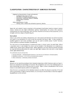
4 A3 - 2 1 METHODS TO DETERMINE THE UNIAXIAL COMPRESSIVE STRENGTH OF ROCKS For some engineering or rock mechanical purposes the numerical characterization of rock material alone can be used, for example boreability, aggregates for concrete, asphalt etc. Also in assessment for the use of fullface tunnel boring machines (TBM) rock properties such as compressive strength, hardness, anisotropy are often among the most important PARAMETERS . For stability evaluations and rock support engineering , however, the rock properties are mainly of importance only where they are weak or overstressed. Though rock properties in many cases are overruled by the effects of joints, it should be brought in mind that their properties highly determine how the joints have been formed, which in turn may explain their characteristics. Although the geological classification of rocks is mainly based on formation and composition of the material, it is so well established that other METHODS for division of this material have not come into major use.
5 Since, in rock mechanics and rock engineering , the rock behaviour rather than its composition is of main importance Goodman (1989) has presented the classification shown in Table A3-1. TABLE A3-1 BEHAVIOURAL CLASSIFICATION OF ROCKS (from Goodman, 1989) GROUPS OF ROCKS Examples I Crystalline texture A. Soluble carbonates and salts .. B. Mica or other planar minerals in continuous bands .. C. Banded silicate minerals without continuous mica sheets .. D. Randomly oriented and distributed silicate minerals of uniform grain size .. E. Randomly oriented and distributed silicate minerals in a background of very fine grain and with vugs .. F. Highly sheared rocks .. II Clastic texture A. Stably cemented .. B. With slightly soluble cement .. C. With highly soluble cement .. D. Incompletely or weakly cemented .. E. Uncemented .. III Very fine-grained rocks A.
6 Isotropic, hard rocks .. B. Anisotropic on a macro scale, but microscopically isotropic hard rocks .. C. Microscopically anisotropic hard rocks .. D. Soft, soil-like rocks .. IV Organic rocks A. Soft coal B. Hard coal C. 'Oil shale' D. Bituminous shale E. Tar sand Limestone, dolomite, marble, rock salt, gypsum Mica schist, chlorite schist, graphite schist Gneiss Granite, diorite, gabbro, syenite Basalt, rhyolite, other volcanic rocks Serpentinite, mylonite Silica-cemented sandstones and limonite sandstones Calcite-cemented sandstone and conglomerate Gypsum-cemented sandstones and conglomerates Friable sandstone, tuff Clay-bound sandstones Hornfels, some basalts Cemented shales, flagstones Slate, phyllite Compaction shale, chalk, marl Lignite and bituminous coal A verbal description of the rock should, in addition to the rock name and its strength, include possible anisotropy, weathering, and reduced long-term resistance to environmental influence (durability).
7 The description of the rock could also contain information on texture, colour, lustre, small scale folds, etc. which can give information to a better understanding of the rock conditions as well as the jointing. A3 - 3 As rocks are composed of an aggregate of several types of minerals with different properties, arrangement and "welding", there are many factors which determine their strength properties. In addition, possible weathering and alteration can highly influence on the final strength properties of a rock. The effect of this is outlined in Section Some minerals have a stronger influence on the properties of a rock than other. In rock construction the mica and similar minerals have an important contribution where they occur as parallel oriented continuous layers (Selmer-Olsen, 1964). Mica schists and phyllites with a high amount of mica show, therefore, strongly anisotropic properties which often influence in rock construction works as shown in Section The uniaxial compressive strength ( c ) In rock mechanics and engineering geology the boundary between rock and soil is defined in terms of the uniaxial compressive strength and not in terms of structure, texture or weathering.
8 Several classifications of the compressive strength of rocks have been presented, as seen in Fig. A3-1. In this work a material with the strength 0,25 MPa is considered as soil, refer to ISRM (1978) and Table A3-1. 700700100100101011 Very weakWeakStrongVery strongCoates1964 Deere and Miller1966 Geological Society1970 Broch and Franklin1972 Jennings1973 Bieniawski1973 ISRM1979 Very low strengthLowstrengthMediumstrengthHighstr engthVery highstrengthVery weakWeakModeratelyweakModeratelystrengSt rongVerystrongExtremelystrongSoilRockVer y lowstrengthLowstrengthMediumstrengthHigh strengthVery highstrengthExtremelyhighstrengthVery softrockSoft rockHardrockVery hardrockExtremely hard rockVery low strengthLowstrengthMediumstrengthHighstr engthVery highstrengthVery lowLow compressive strength, MPa Fig. A3-1 Various strength classifications for intact rock (from Bieniawski, 1984) The uniaxial compressive strength can be determined directly by uniaxial compressive strength tests in the laboratory, or indirectly from point-load strength test (see Section ).
9 The tests should be carried out according to the METHODS recommended by the ISRM (1972). The classification of the uniaxial compressive strength suggested by ISRM is shown in Tables A3-1a and A3-7. A3 - 4 TABLE A3-1a CLASSIFICATION OF THE UNIAXIAL COMPRESSIVE STRENGTH OF ROCKS ( c ) (from ISRM (1978) ---------------------------------------- ---------------------------------------- ------------- Soil c < MPa Extremely low strength c = - 1 MPa Very low strength c = 1 - 5 MPa Low strength c = 5 - 25 MPa Medium strength c = 25 - 50 MPa High strength c = 50 - 100 MPa Very high strength c = 100 - 250 MPa Extremely high strength c > 250 MPa ---------------------------------------- ---------------------------------------- ------------- The uniaxial compressive strength of the rock constitutes the highest strength limit of the actual rock mass.)
10 ISRM (1981) has defined the uniaxial strength of a rock to samples of 50 mm diameter. A rock is, however, a fabric of minerals and grains bound or welded together. The rock therefore includes microscopic cracks and fissures. Rather large samples are required to include all the components that influence strength. When the size of the sample is so small that relatively few cracks are present, the failure is forced to involve a larger part of new crack growth than in a larger sample. Thus the strength is size dependent. This scale effect of rocks has been a subject of investigations over the last 30 to 40 years. Fig. A3-2 shows the results from various tests compiled by Hoek and Brown (1980) where the scale effect (for specimens between 10 and 200 mm) has been found as c = c50 (50/d) eq. (A3-1) where c50 is for specimens of 50 mm diameter, and d is the diameter (in mm) of the actual sample.