Transcription of MICROCOUPLING - 大同精密工業株式会社
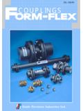
1 MICROCOUPLING . Daido Precision Industries Ltd. 3 Fl. Nishi-Ikebukuro TS BLDG., 1-15 Nishi-Ikebukuro 3-Chome, Toshima-ku, Tokyo 171, Japan Tel. 03-5956-9176 Fax. 03-5956-9177. Daido Precision Industries Ltd. Popularity Gained Through Use In Various Fields Such As Mechatronics, And Others MICROCOUPLING are: Examples Of Application Compact size plate spring type precision shaft coupling that have made debut in the first place in Japan. Plate springs vital to this type shaft coupling are deriva- tive from sheet metal fabricating technique, the expertise unique to us being accumulated for nearly one half a century.
2 Making debut in 1975 and with acquired abundant expe- 1. No Back-lashing 4. High Power For Absorbing Of MICROCOUPLING Connecting a motor shaft and rotation detector such as for servo-motors. Driving feed screws in NC machine tools, industrial robots and the like. Precision positioning in X-Y tables, mea- rience and providing good results since, MICROCOUPLING are suring instrument, office automation now used widely in variety of fields such as measuring instruments and machine tools, robots, semiconductors and Component parts mechanically connected afford for precise rotation Eccentricity/Declination equipment, semi-conductor processing units and the like.
3 So on that are leading the era's industries. control. High fatigue resistance of plate springs allows for provision Wide products line, ranging from High precision, high of a high power for absorbing eccentricity and declination. torque products to reasonably priced products. Products Increasing distance between plate springs allows for making homogenized in quality meeting the needs of the era derived from a vertically integrated production system form design- higher power for absorbing eccentricity without changes take ing through manufacturing to inspection. place with power for absorbing eccentricity, thus facilitating centering.
4 High Torsional Rigidity 2 TOKUSHU SEIKO. MICROCOUPLING 5. M Series Utilization of resiliency, a property of plate springs, provides high resonance frequency and precise (Standard Type). Longer Useful Life Dispense V Series responding characteristic. (Enhanced Torque Type) With Maintenance Microflex Having no sliding parts eliminates wearing, thus allowing U Series continuous operation for extensive period of time without (Low Torque . Low Cost Type Super Small Size). lubrication. 3. Greater Torque Capacity 6. Transmission of torque developed by plate springs as Greater Degree of Freedom simple tractive force allows for provision of greater torque capacity as compared to those using shearing For Each Part strength.
5 Connecting respective parts based upon machine elements Use of high tensile steel provides tenacity against intense allows changes in parts composition, thus meeting all needs right and reverse rotation. arising depending upon application. 1 2. MICROCOUPLING For High Precision And High Quality Without Backlash Product Line Series Representation System of Products Axial Directional Displacement and Allowance for Declination M Series V Series U Series M 1 A - 10 K / 15 K - (mm). Axial Directional Displacement Series Standard Type Enhanced Torque Type Low-torque, Low-cost Type Suffixed Symbol Torque ~15 6~20 ~ =Accessories M1.
6 M2. =Product on Optional Specification M3. Material Aluminum Alloy Carbon Steel Aluminum Alloy Shape of Bore in Hub M4. 0 ( ). (See Drawings for Shape of bore in Hub). Declination Major Application Servo System Rotation Detector Servo-motor General Rotation Detector S=Set-screw System K=Set-screw with Key Way System Allowance for declination varies depending upon Servo-motor Feed Screw Small Size Motor BC=Clamping System axial directional displacement Feed Screw Small Size Feed Screw BCK=Clamp with Key Way System Longer useful life will be achieved by maintaining axial T=1/10 Taper with Key Way System directional displacement and declination within the values above D=Stepped Bore System Axial directional displacement represents a value
7 Per one set of Selection Base Model Number Reference Table for Selection (M, V Series) (U Series). Diameter of Bore in Hub coupling. Declination represents a value per one set of flexible <Unit:mm>(See "C Dimension" in the Specification). 1. Transmission of Torque plates.(plate springs). Select a coupling so that a design torque as derived Type (See shaft Fixing Diagram on the Left). from following formula to be within a rated torque A=Standard Length, shape of bores in hubs on both sides are in set-screw system. F=Shortened Length, shape of bores in hubs on both sides are in set-screw system.
8 Axial Directional Displacement for such a coupling. AC=Standard Length, shape of bores in hubs on both sides are in clamping system. FC=Shortened Length, shape of bores in hubs on both sides are in clamping system. and Thrusting Force (N). AB=Standard Length, shape of bore in hub on one side is in clamping system and that in another side is in 1/10 taper system. Thrusting Force FB=Shortened Length, shape of bore in hub on one side is in clamping system and that M1. in another side is in 1/10 taper system. T= X P XK. N Rated Torque( ) Rated Torque( ) Model Number (See Table of Selection Base on the left) M2.
9 M4. Series (See Product Line System on the Left) M3. T ( ) = Design Torque M=Standard Type (Aluminum alloy) 0 (mm). P (W) = Rated Output Structural Diagram V=Enhanced Torque Type (Carbon steel). U=Low Torque . Low Cost Type (Super Small Size) (Aluminum alloy). Axial Directional Displacement Greater axial directional displacement is N (min-1) = Rated Rotating Speed Letters and numerals used in in above example are in accordance with the following setting: absorbed by lesser thrusting force K = Load Coefficient Series=M Series Model Number=1 Axial directional displacement and thrusting force, respectively Type=Of standard Length and in set-screw system for both hubs A represents a value per one set of coupling.
10 (K=3, for Servo-motor Driving) Diameter of shaft hole in hub= 10 and 15 Thrusting force is proportional to axial directional displacement. Shape of bore in hub=set-screw with key way system K. Torque and Torsional Angle 2. Transmission of Rotation For driving measuring instrument, select a coupling Shape of bore in Hub (minute). 15 M4. with consideration of performance characteristics Torsional Angle and allowable load, in main, and relative variation S K BC 10. in two working shafts and centering precision. M3. 5 M2. shaft Fixing system Type Model and Type 0 1. M1. (N m). Torque Model A Type (Standard Length) *Note F Type (Shortened Length) *Note Series A F AC FC AB FB BCK T D High torsional rigidity can be enhanced further Torsional angle is proportional to torque M1 - - Torsional angle represents a value per one set of coupling M2 - - Note) Above diagrams are examples of observed Set-Screw System Set-Screw System Set-Screw System Set-Screw System values for M Series.
