Transcription of Micropile Installation Methods and Selection.ppt
1 1 Micropile InstallationMicropile InstallationMethods and SelectionMethods and SelectionDr. Donald A. BruceDr. Donald A. BruceAgenda1. Drilling in Rock and Flushing Monitoring While Drilling2. Classification of Micropiles Based on Grouting Means, Methods and QA/QC3. Storage Handling and Placement of Reinforcement4. Growth of the Micropile Market in the Final Remarks2 ScopeScope and Commonalities1. Drilling in Rock and Methods Typically 3 to 12 inch diameter. Typically 200 foot depth. Typically within 30 of vertical or horizontal. Mostly beneath the water table. Required in all types of ground, natural or placed, unconsolidated or lithified, and will often encounter ,andwilloftenencounterobstructions. May face Federal regulations, , USACE 1997. Must cause minimal damage to the ground or existing structures.
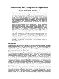
2 Must allow completion of the hole in one day. Must be consistent and able to be controlled and monitored. Generally contractor driven ( performance specification). Continuous, straight penetrationScope and Commonalities (continued) Constant diameter, stable and clean bore Consistent with the purpose of the drill hole ( , grout hole vs. anchor hole) Appropriate combinations of thrust, torque, rotation, percussion, flush CosteffectiveCost effective Dictated by ground, not historical bias Environmentally compatible3 Evolution of Rock Drilling MethodsDawn of the ADSC AgeBasic drilling method selection guide for rock using noncoring Methods ,Littlejohn and Bruce, 1977 (adapted from McGregor 1967). rotary High rpm, low torque, low thrust (blind or core)Rock Drilling Methods (Disco Era) Low rpm, high torque, high thrust rotary Percussive Top Hammer Down the Hole Hammer Direct circulation Reverse circulation Dual fluid drilling Water hammers rotary Vibratory (Sonic)4 Overburden Drilling MethodsOVERBURDENDRILLING METHODSO verburden isOverburden isOVERBURDENDRILLING METHODSO verburden isOverburden isOverburden isSTABLE*Overburden isUNSTABLE*SolidStemAugerOpen Hole(with RockDrillingMethods)HollowStemAuger Combination MethodsSlurrySupportedMethodsCasedMethod sLOW ----- Presence of -- SEVEREO bstructionsHIGH -- Environmental ---- LOWC oncernsSonicSingleTubeRotaryDuplexRotary PercussiveDuplex(Eccentric)DoubleHeadDup lexBentonitePolymerSelfHardeningRotaryPe rcussiveDuplex(Concentric)
3 Overburden isSTABLE*Overburden isUNSTABLE*SolidStemAugerOpen Hole(with RockDrillingMethods)HollowStemAuger Combination MethodsSlurrySupportedMethodsCasedMethod sLOW ----- Presence of -- SEVEREO bstructionsHIGH -- Environmental ---- LOWC oncernsSonicSingleTubeRotaryDuplexRotary PercussiveDuplex(Eccentric)DoubleHeadDup lexBentonitePolymerSelfHardeningRotaryPe rcussiveDuplex(Concentric)VERY HIGH ---------------------------------------- ---------------------------------------- ---- Instantaneous Penetration Rate Potential ---------------------------------------- ---------------------------------------- -- LOWERLOW ---------------------------------------- --------------------------------- Technological Sophistication ---------------------------------------- ------------------------------- HIGHLOW ---------------------------------------- ----------------------------------- Presence of Obstructions ---------------------------------------- ----------------------------- SEVERE*Stability refers to the overburden s ability to maintain the shape and size of the drilled hole without detriment to thesurrounding ground after withdrawal of the drilling drill method selection guide for
4 Overburden (Bruce, 2003).Notes on the 2003 Classification Basic subdivision is stable vs. unstable. Stable overburden can be drilled with SSCFA or rock drilling Most overburden is unstable especially when holes are long and in difficult urban settings. Unstable Methods are subdivided into 4 but be Combination Methods can offer original and effective Methods ( , rotary with air).project supported Methods organic polymers offer considerable advantages over Methods now DTH usually superior to Top Drive or rotary in Rock penetration rates per foot costsdiilSome Evolutionary Notes deviation control large diameter (< 40 inches) to greater depths (> 300 feet) Very sophisticated computer programs/simulations optimize design for speed, durability, reliability and for special applications ( short hammers and highfrequencyhammers)high frequency hammers).
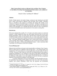
5 PISTON(34 LBS)BIT(33 LBS)New Piston Bit Combination (Equal Mass)New Simple, High Frequency RX HammerNew Simple, High Frequency RX HammerSome Evolutionary Notes(continued) Air pressures have increased from 160 250 psi in 1970 s, to up to 500 psi td Better understanding of metallurgy of components and bits. More widespread use of reverse circulation. More widespread use of water powered DTH s efficiency, lower flushing velocities, straighter holes. Use of rotary vibratory Methods (Sonic) but mainly for overburden, only true innovation to come to the drilling industry since the Chinese invented cable tool drilling some 3,000 years ago (Roussy, 2002).6 More Recent DevelopmentsThese include: Numa Superjaws featuring 2 4 wings which open by pressure on thefaceoftheholeDirect Atlas Copco Elemex system a ring on the casing redirects the air flush away from the DTH bit face and so makes it easier to control.
6 CenterRock Rotoloc system featuresapatentedmethodofthe face of the hole. Direct descendent of old Acker Casing Underreamer Rock Rotoloc system features a patented method of extending, locking and retracting cutting wings on the central pilot bit, in a very simple and reliable fashion. Does not rely on downwards pressure on the face and leaves nothing behind in the Lock (retracted)Roto Lock (extended)7 Up hole velocity (UHV) > sinking velocity In water, sinking velocity (Vz) is Vz 106x d2m/s where d is the diameter of the Flushing Characteristics Ability of flush to carry or suspend cuttings dependent on: rate of flow of fluid Viscosity of fluid size and shape of cuttings of fluid and cuttings UHV (m/min) = lh(/)1274 x Flush Pump Rate (Liters/min)D2 d2(mm)where D = drill hole diameter (in mm)d = drill string diameter (in mm)Acceptable Up hole FlushCharacteristics Air vs.
7 Water rotary vs. RotaryPercussionRotary Percussion Guideline for selection: Provide clean hole Enhance penetration rate Minimize tool wear Consistent with purpose of hole Minimal damage to formation and/or structures Environmentally compatible Reconsider options if lost flush Monitoring While Drilling Fundamental Concept Manual Monitoring Automated MonitoringBfiOdC(dihi Benefits to Owner and Contractor (not covered in this presentation)9 Fundamental ConceptEveryholethatisdrilledintheground isapotentialsourceofBasic Principles of Monitoring While Drilling (MWD)Every hole that is drilled in the ground is a potential source of information on the properties and response of the ground. This obviously applies to designated site investigation holes, but is equally true of every production hole, such as drilled for anchors, micropiles, nails or grout holes.)
8 Such information can be collected by two basic Methods : ymanual and automatic. The data must be studied in real time to be :1. Helps determine or verify appropriate bond zone horizons for anchorsand and higher order holes will demonstrate progressive densification of ground in compaction Helps select appropriate jet Will provide a mechanical and hydraulic picture of the rock mass at each phase of a grout MonitoringBasic Principles of Monitoring While Drilling (MWD) The value of routine drillers logs can be greatly enhanced by periodic recording of:of: penetration rate thrust torque flush return characteristics (cuttings, volume) drill action interconnections between holes hole stabilityy groundwater observations These data can easily be recorded by a good driller who has been briefed about the overall purpose of the project and so understands what to look for.
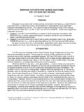
9 These data should be recorded at 5 ft maximum Recording of Drilling Progress and Parameters Value of real time continuous monitoring for design purposes Basic Principles of Monitoring While Drilling (MWD)ggpp(manual vs. automatic) Look for exceptions and unexpecteds [Weaver, 1991] Indication of progressive improvement ( , denser, less permeable conditions)Ctfifi Concept of specific energy Several generations/evolutions as software and hardware evolve11 Automated MonitoringCalculation of Specific Energye=F+2 N TAAR wheree = specific energy (kJ/m3)F= thrust (kN)A=crosssectionalareaofhole(m2)Across sectional area of hole (m2)N= rotational speed(revolutions/second)T = torque (kN m)R = penetration rate (m/sec)Grouting and Grout Function2. Grouting Classification of Micropiles Based on Grouting Method Transfers loads from reinforcement to surrounding ground May be load-bearing portion of pile Protects steel reinforcement from corrosion May be used as drill fluid during initial drilling Secondary/Post grout enhances soil/grout bond further Basis for Micropile Classification12 Classification Based on Grouting Method Type A: Gravity Type B: Pressure grouting through casing Type C: Single, global post grout Type D: Multiple Type D: Multiple, repeatable post grout Type E.
10 Injection bore bars Grout introduced into the drill hole through a tremie pipe exiting at the bottom of the holeGravity Filling Techniques (Type A)exiting at the bottom of the hole No excess pressure is applied This type and phase of grouting is referred to as the primary treatment Typically only used when pile is founded in rock, or when low-capacity piles are being installed in stiff or hard cohesive soils13 Pressure Grouting Through the Casing(Type B) Grout injected under controlled pressure through pressure cap on top of drill casing (often the drilling head itself) Additional grout injected under pressure after primary grout has been tremied (as temporary casing is withdrawn) Enhances grout/soil bond characteristicsEnhances grout/soil bond characteristics Can be limited to the load transfer length within the design-bearing stratum, or extended to the full length of the pilePost-Grouting (Types C and D) Additional grout injected via grout tubes after placing gjgpgof primary grout Higher water content grout used(w/c ratio = to ) High pressures used (> 1 MPa) Type C only used in France to date14 Type E MicropilesClose up of Bit (Injection-Bore Threaded Bar)Typical Grouting Means, Methods and Materials Neat cement grouts with water/cement ratios of to Potable water used to reduce corrosion potential Type I/II cement (ASTM C150/AASHTO M85)