Transcription of Microwave and RF Cable Assemblies: The Neglected System ...
1 Cable PerformanceMicrowave and RF CableAssemblies: The NeglectedSystem ComponentPart 2: Operational Considerations of the Coaxial AssemblyBy David SlackTimes MicrowaveWe ve discussed some of the typi-cal electrical characteristics of acable assembly, and some of theenvironments typically aspects affecting the optimumdesign of a coaxial Cable assembly arecovered handlingPower handling of an RF ormicrowave assembly can be separatedinto two distinct classifications: averagepower and peak power. Many RF andmicrowave Cable assemblies can handlepower levels of several kilowatts whenthe duty cycle is very low. This wouldtypically be encountered in RADAR applications where a pulsed transmitteris used. It can be assumed, if the duty cycle islow enough, that the average power effects canbe effectively ignored. When this is true thenthe failure modes are arcover due to voltagebreakdown and corona formation is caused when the electricfields present within the Cable assembly ionizeoxygen that is trapped in microvoids within theassembly.
2 The corona induces noise into the sig-nal that is being propagated and is the precur-sor to a voltage is highly charged and is thereforequite conductive. As charge densities increase,in proportion to higher power levels, coronalevel increases. As these levels are increased fur-ther a point is reached where a conductive pathis formed between the conductors of the assem-bly. It is at this point that an arcover conditionoccurs. An arcover is a destructive condition inthat it leaves a carbonized path in its wake thatis conductive, and thus a short circuit (or partialshort depending on the severity of the arcover)is indelibly left within the Cable of this nature typically occur at thecable/connector junction. This is normallywhere the inner and outer conductors are clos-est together and are least the judicious selection of connectorgeometries, and through the use of overlappinginsulators within the connector, peak powerhandling capabilities are maximized.
3 Whenhigher duty cycles are required, the averagepower effects begin to become the limiting fac-tor. This can range from high duty cycle pulsedpower to CW power (duty cycle = 100 percent).Average power handling capability is directlyrelated to a Cable assembly s ability to transferheat to its external RF and Microwave Cable assemblies havean attenuation factor associated with them. As aresult of this attenuation, a portion of the powerdelivered from a source is dissipated within thestructure of the Cable assembly. Because of thelimited ability to transfer heat from internal62 Applied Microwave & WirelessnTypical vapor sealed Cable assemblies , showing stainlesssteel connector bodies and Nomex Cable Performance64 Applied Microwave & Wirelesscomponents, the assembly will undergo a temperatureincrease. The point where the centerconductor tempera-ture approaches the melting point of the dielectric is gen-erally considered the limit of a Cable s average powerhandling.
4 This limit is approximately +200 degrees C forTeflon dielectrics and approximately +100 degrees Cfor Polyethylene mechanisms used to transfer heat are conduc-tion, convection and radiation. Conduction is generallythe most efficient method of transferring heat from acable. This would be transferred through the conductorsof the Cable , into the connectors, and into the matingequipment. This tends to keep the ends of the cableassembly cooler and works best when a large tempera-ture gradient exists between the assembly and the mat-ing is the second most efficient method oftransferring heat from a Cable assembly. This heat trans-fer is due to movement of air around the assembly and isvirtually nonexistent at high altitudes. The third method,radiation, is the primary means of heat transfer at highaltitudes. Radiation efficiency is a function of the emmi-sivity of the outer surfaces of the Cable assembly and canbe maximized by using black materials with a dull maximize average power handling, the selectedcable should have the very minimum insertion loss,maximum outer surface area and a highemmisivity jacket.
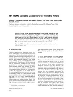
5 Careful selection ofcable routing is of primary importanceas well. A Cable that performs in a wellventilated area may suffer catastrophicfailure when ventilation is same holds true when consideringthe ambient temperature of the cablesenvironment. The temperature gradi-ent between the Cable assembly and itssurroundings is fundamental to theassembly s power handling of the infinite nature ofoperating environments, specifiyingpower handling capability of an assem-bly can be a rather ambiguous System designer should use a gener-ous engineering margin when selecting power 1 shows typical power handling capabilities ofa vapor sealed " diameter Cable with a braidedNomex , replacement, maintenance activities andother practicalities tend to dictate the use of a flexiblecable. Quite often, when harsh environments are beingdesigned for, ruggedization causes flexibility to be com-promised.
6 With proper design, this type of trade-off doesnot have to be inherently rugged dielectric core constructionwith a combination of strip and braid outer conductorgeometries, along with advanced vapor sealing tech-niques, a Cable is produced that will withstand harshenvironments while exhibiting a bend radius less than10 times its outer diameter. Multiple flexing cycles ofthis Cable cause no degradation of the phase, VSWR orinsertion loss characteristics of this of this construction, having a inchouter diameter, can undergo many wrap/unwrap cyclesaround a two inch mandrel and will phase track eachother to well within 6 degrees at 18 2, 3 and 4 show the effects of this flexing onone of these and altitude extremesDesigning a Cable assembly for use in wide tempera-ture extremes involves appropriate material choices,mechanical structures that allow for thermal expansionand contraction, and connector designs that include con-tact captivation to constrain excessive physical test assembly performance at temperature and alti-tude extremes.
7 Several tests are commonly thermal shock test involves stabilizing an assemblyat one temperature extreme then quickly replace it intoan environment that is at the other temperature extremeand allow it time to stabilize. This would constitute onecycle of a thermal shock test. Stable, vapor sealed assem-blies have been built and tested that endure 5 shockcycles between 62 degrees C and +125 degrees C andmaintain phase tracking to within 6 degrees between1227 864 704 608 543 495 457 427 402 381 363 347 333 321 309 299 290 282902 636 518 447 399 364 336 314 296 280 267 255 245 236 228 220 213 207603 425 346 299 267 243 225 210 198 187 178 171 164 158 152 147 143 139 Frequency (GHz)123456789101112131415161718@ Sea Level@ 35,000 Ft.@ 70,000 Maximum Power Handling inch outer diameterAmbient Temperature = +25 CMaximum Power (Watts)nFigure 1.
8 Typical power handling Cycles2030405060708090100110120 VSWRVSWR vs. FlexureVSWRnFigure 2. VSWR variationvs. Performance66 Applied Microwave & Wirelesseach cycle as well as after completion of the full test. TheVSWR and insertion loss characteristics remained with-in their specification tolerances as same assembly has also been evaluated where thetemperature extremes are maintained while the assem-bly is placed in a vacuum simulating altitudes of 70,000feet. These assemblies operate continuously under theseconditions and maintain the electrical performance char-acteristics of loss, VSWR and phase conditionsAside from the extremes of temperature, altitude andvibration that a Cable assembly might see, there areother atmospheric conditions that may affect the assem-bly. Many systems are required to operate in highhumidity levels for long periods of time. This is primar-ily a sealing issue. If there are even very small leaks inthe assembly, moisture will ingress into the conductivepath of the assembly.
9 This moisture ingress is exacer-bated by changes in altitude and temperature. A com-mon example would be an airplane coming in for a land-ing, where often condensation forms on the Cable assem-bly as the ambient pressure rises. The increasing pres-sure tends to force the surface moisture into the cableassembly. Any moisture in the conductive path will seri-ously degrade the performance of the Cable assembly. Many times the environment is salt spray or salt would be typical in installations aboard ships orboats as well as operating areas that are in close prox-imity to ocean areas. With a salt fog environment, thesealing issue is still fundamental, but there is an addedthreat of corrosion of the metallic surfaces of the assem-bly. Careful selection of metals and metal finishes is crit-ical when dealing with corrosive atmospheres. A pru-dent corrosion control program ensuring high qualityplating and finishes on all components of the cableassembly is and maintainabilityOftentimes, when an RF assembly is optimized elec-trically, it is rendered quite fragile mechanically.
10 A highperformance coaxial assembly is more valuable if it canbe easily installed and still perform to its design para-meters. In addition, an assembly should survive mainte-nance to surrounding equipment as well. Often a coax isinstalled into a bundle of other cables and other activities take place, the bundle can becrushed, stepped on, have equipment dropped on it, evenhave hydraulic fluid or gasoline spilled on it. Once anassembly is installed, and other structures installedaround it, making it quite inconvenient (and expensive)to replace ensure that a Cable assembly can be adequatelyclamped in place a clamping pressure test should be per-formed. A typical clamping pressure test is to place aportion of the Cable into a fixture that will place a 50 psiforce around the circumference of a two inch length ofthe electrical parameters of the assembly are moni-tored while this force is maintained for several degradation of the electrical characteristics wouldnEngineering evaluation of vapor sealed Cable assemblycomponents is critical to the optimization Cycles2030405060708090100110120 Phase Change vs.