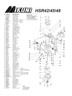
Transcription of Mikuni HS40
1 Mikuni HS40 Tuning manual , Exploded View and Parts ListFigure 1: Diagram showing the effective range of the each tuning component of the Mikuni HS40 carburetorIDLE CIRCUIT (PILOT SYSTEM) The idle circuit supplies fuel at idle speeds and has a major influence on fuel flow up to 1/4 throttle. There are three tunable parts in the idle circuit:1) PILOT JET --- controls maximum fuel flow through the idle ) PILOT AIR JET--- controls the maximum amount of fuel that will flow through the pilot jet by allowing a higher (smaller air jet) or lower (large air jet) vacuum signal at the pilot ) PILOT SCREW --- controls how much fuel is allowed to enter the carburetor venturi. The pilot screw is used to control idle mixture. Turn the screw out to richen the idle mixture.
2 Turn it in to lean the mixture. The engine should have a smooth, steady idle with the screw between 1/4 and 3-1/2 turns out from fully bottomed (gently!). If the engine requires more than three turns out, the pilot or pilot air jet may be too lean. If it requires less thatn 1/4 turn, it may be too rich. As the throttle is opened the pilot screw s position becomes less important than the sizes of the pilot and pilot air jets. A larger pilot jet richens the mixture from just off-idle to 1/4 throttle. A smaller one leans it. A change in pilot air jet has the reverse effect. A larger pilot air jet leans the mixture and a smaller one richens it. The pilot jet and pilot air jet have slightly different effects on mixture strengths. These effects are discussed in the General Tuning Procedure portion of this manual .
3 The idle circuit can be adjusted by changing either the pilot or the pilot air jet. A one-size larger pilot jet will have nearly the same effect as a one-size smaller pilot air jet. It is generally easier to change the air jet since it is more accessible. After changing either jet, it is necessary to re-adjust the pilot screw for best SYSTEM The main system dielivers fuel from 1/16 to full throttle. The idle circuit delivers the mahority of the fuel near 1/16 throttle. The main system becomes the important mixture control from about 1/4 throttle. The main system has three tunable parts:1) NEEDLE JET --- controls mixture from 1/16 to approxi-mately 1/4 throttle (varies with needle position).2) JET NEEDLE --- controls mixture from 1/4 to 3/4 ) MAIN JET --- controls mixture from 3/4 to full throtle The jet needle has a constant diameter section and a tapered section.
4 The diameter of the needle and the inside diameter of the needle jet form an orifice through which all main system fuel must flow. Until about 1/4 throttle, the constant diameter sec-tion of the needle is within the needle jet and main system fuel flow is controlled by the size of the needle jet. Needle jets are available with different inside diameters. A larger needle jet richens the mixture within its range of operation. Notches at the top of the needle allow it to be raised or lowered. Raising or lowering the needle deter-mines the throttle setting at which the tapered part of the needle is raised out of the needle jet. Main system fuel flow is controlled by the needle s taper from where it begins to lift out of the needle jet until about 3/4 throttle.
5 Raising or lowering the needle respec-tively richens or leans the mixture from that point until the main jet becomes effective. At about 3/4 throttle the orifice formed by the needle and needle jet becomes large enough that the size of the main jet begins to control fuel flow. Until this point the main jet has no effect on mixture strength. At full throttle the needle taper has little or no PUMP Mikuni s HS40 carburetor is fitted with an accelera-tor pump. The purpose of the pump is to inject fuel into the throat of the HS40 when the throttle is opened. As the throttle is opened, especially at low rpm, air velocity through the carburetor drops and the mixture naturally becomes leaner. Fuel from the pump maintains a more correct fuel/air mixture until the air velocity returns to normal.
6 The accelerator pump can be adjusted to inject fuel into the throat of the carburetor over a wide range of throttle openings. The rate at which it injects fuel can also be controlled with different sized pump nozzles. Total flow volume depends upon the pump s beginning and end point Systems: DescriptionFigure 2: Diagram showing float level range and checking SYSTEM Mikuni s starter system takes the place of the crude choke mechanism of the stock carburetor. It is actually a small auxilliary carburetor designed to supply a rather rich mixture for starting purposes. The starter system only works when the choke knob is pulled open and when the throttle is closed. If the throttle is opened with the choke knob pulled out, air essentially ceases to flow through the starter system and it stops delivering its rich mixture to the engine.
7 If the engine begins to load-up while the starter system is engaged, it may be cleared by opening the throt-tle. When the throttle is closed, the starter system resumes operation. The starter system has one replaceable compo-nent, the starter jet. A larger starter jet makes the starter mixture richer and a smaller one makes makes it leaner. The #55 jet fitted to the HS40 will suit most installations. However, if you live in a warm climate, the alternate #45 jet may perform ) Throttle return spring adjustment: The throttle return spring has 3 pre-load positions. The HS40 is supplied with the spring in the stronger of the 3 positions. You may wish to try a weaker spring position. However, in some installations, the softer spring position may result in erratic return to ) Fuel float adjustment: Fuel float level is critical to proper operation of any carburetor, the HS40 is no exception.
8 Mikuni correctly adjusts the floats during assembly but they may be acciden-tally bent out of adjustment during tuning or other handling. If you have doubts, check the float level and re-adjust if needed. A float level that is too high can make fine tuning of the idle circuit impossible. One that is too low will have a similar effect on mid-range TUNING PROCEDURES Your Mikuni is fitted with the tuning parts we found to work with a majority of engine tuning combinations. How-ever, the tremendous number of differing exhaust systems and cams available for Harley engines make it impossible to accommodate all possible combinations with one carbure-tor set-up. You will probably find that the HS40 will run perfectly on your engine without exchanging any parts.
9 But if it doesn t, you may alter its tuning to suit your engine s needs by following this guide. There are many more replaceable parts that affect tuning in the HS40 than in the stock Harley carburetor. With these parts you can precisely tailor the HS40 s tuning to your engine s requirements throughout its rpm and throttle setting range. Each tuning system is easy to modify and diag-nose, but only when you understand what each system does and how it works. Before making any alterations to the HS40, if any are needed at all, read the section of this manual describing the various components and their functional range. There is simply no point in attempting to tune any carburetor unless the engine is completely sound. Valves and rings must seal properly, the ignition timing must be correct and the spark plugs clean and gapped.
10 Some exhaust systems may also make carburetor tuning difficult. For instance, it is almost impossible to get smooth respon-sive carburetion with straight and open pipes. If you have and doubts about the condition of your engine, tune and test it before beginning what could be a frustrating and unproductive effort to fix another problem with the THE IDLE CIRCUIT (PILOT SYSTEM) The first step in tuning any carburetor is to get the idle circuit correctly adjusted. And, the first step in this procedure is to adjust the pilot screw position for best idle. Mikuni sets the pilot screw at three turns open during assembly. This is the position we have found to be right most of the time. If the screw position has been altered, gently bottom it and re-open to three turns out.

