Transcription of MIL-DTL-38999 Series III - Benchmark Connector
1 DTL 38999 S III MIL-DTL- 38999 Features and ApplicationSeries and ApplicationMIL-DTL- 38999 Series III is the newest cylindrical connectordesigned for highest performance capabilities used in bothgeneral purpose and severe environment connectors feature an improved one-turn couplingsystem, utilizing self-locking acme thread. Acme threadsprovide coupling durability, while thicker wall sections andgreater coupling surface area improve strength and shockresistance. Blunting of the threads on both receptacle andplug coupling nut eliminates cross mounting holes permit the Series III Connector tointermount with various existing Mil-spec flange mountedreceptacles, giving it a design replacement mount receptacle, jam nut receptacle and straight self-locking RFI plug are offered in 9 shell sizes and 54 insertarrangements utilizing M39029 contacts in sizes 22D, 20, 16,12, 10 power and 8 connectors are available in wide range of shell materialsand finishes.
2 Aluminum shells are offered in electroless nickeland olive drab cadmium. Other finishes such as anodic andzinc nickel are available upon request to commercial calloutsonly. In addition, we offer stainless steel shells (both passivatedand electro-deposited nickel plated) with firewall inserts, andfor highly corrosive environments, nickel-aluminum-bronzeshells with standard environment-resisting inserts (commer-cial callouts only).MIL-STD-1560 Insert Arrangements Series III connectorsuse insert patterns and contacts common to Series I, making for an easy transition from bayonet to triple-lead,acme-thread, self-locking Bottoming This feature precludes relativeshell-to-shell motion, which may result in ordinary connectorwear and moisture Eliminated Self-locking quick coupling plugeliminates the need for Capability -Stainless steel shells in both K and Sfirewall classes are I/R Tool A single, expendable plastic tool is usedfor both insertion and removal of contacts.
3 Scoop-Proof Design Recessed pins in elongated shellsminimize the possibility for contact damage. In a blind mating application, mating shells cannot scoop the pins,and cause a shorting or bending of contacts. Closed-Entry Socket Insert Hard dielectric socket facehas lead-in chamfers for positive alignment of pins (evenpartially bent within pre-established limits) with Pin Insert Seal Raised moisture barriersaround each pin, which mate into lead-in chamfers of hard face socket insert, provide individual contact seal is never touched by service Wire Sealing Grommet Sealing over a widerange of wire diameters is assured by a triple wire seal ineach cavity at the rear of the Connector . Superior Contact Stability Rear release crimp contactsystem features a stamped beryllium-copper retaining clipcaptivated by molded-in shoulders of each contact cavity inthe insulator.
4 A rear-inserted M81969 plastic tool expandsthe tines beyond the shoulder, releasing the contact. Metric Accessory Thread Metric thread results in additional wall thickness giving greater strength and DTL 38999 S IIIMIL-DTL- 38999 Performance SpecificationsSeries III Performance SpecificationsOperating Temperature RangeClasses F, K, S and BZ*: -65 C to +200 C (-85 F to +392 F)Classes W and ZC*: -65 C to +175 C (-85 F to +347 F)Material and Finish Data (Class)F aluminum shell, electroless nickel finishK stainless steel shell, passivated, firewallS stainless steel shell, electrodeposited nickel, firewallW aluminum shell, olive drab cadmium over nickel baseBZ* aluminum nickel bronze shell, std insertZ* aluminum shell, zinc nickel finishCorrosion ResistanceClasses K, W, BZ* and Z* withstand 500-hour salt F and S withstand 48-hour salt of 500 mating ResistanceConnectors resist specified immersions in MIL-PRF-7808,MIL-PRF-23699, MIL-PRF-5606, M2-V Chevron oil, Coolanol25, MIL-DTL-83133 (JP-8), MIL-DTL-5624 (JP-4, JP-5),SAE-AMS1424 Type I, and other solvents and cleaning EffectivenessRFI and EMI attenuation at the specified frequencies meetthe requirements of MIL-DTL- 38999 .
5 RFI shielding effectiveness of mated connectors with RFIbackshells is measured in a triaxial radio frequency leakagefixture. EMI shielding effectiveness is measured at the interfaceof mated connectors and tested by the mode-stirredtechnique specified in method 3008 of RatingEnvironmental SealWired, mated connectors with specified accessories attached, shall meet the altitude-immersion test specified ConductivityMaximum potential drop shall not exceed: Classes F and S = millivolt. Class W = millivolts, Class K = millivoltsShock and Vibration RequirementsWired, mated connectors shall not be damaged, nor shallthere be a current interruption longer than one microsecondwhen subjected to the following: ShockPulse of approximate half sine wave of 300 G 15 percent mag-nitude with duration of 3 1 milliseconds applied in three Impact ShockWhen mounted as specified in MIL-S-901, grade A, a drop of a 400 lb.
6 Hammer from 1 foot, 3 feet and 5 feet applied toconnector in three axes, totaling nine and mated connectors withstand the following vibration levels: Sine vibration where Connector samples with simulatedaccessory load are subjected to simple harmonic motionfrom 10 to 2,000 Hz in three mutually perpendicular axes,in 20 minute sweeps, for 12 hours in each axis at velocity of254 mm/sec from 10-50 Hz, displacement of mm from50-140Hz and acceleration of 60G from 140-2,000Hz. Random Vibration per MIL-STD-1344, method 205, test condition V at ambient temperature and test condition VI, Letter J at elevated temperature.* Not on QPL, can be supplied to Aero-Electric part number Operating VoltageTest VoltageTest VoltageTest VoltageTest Voltage(Sea Level)Sea Level50,000 ,000 ,000 (RMS)DCV RMSV RMSV RMSV RMSM4005501300550350200N3004501000400260 200I6008501800600400200II900125023008005 00200 Note: The establishment of electrical safety factors is leftentirely to the designer, as he is in the best position to knowexactly what peak voltages, switching currents, transients, etc.
7 ,can be expected in a particular DTL 38999 S IIIMIL-DTL- 38999 Part Number DevelopmentSeries IIIM ilitary and Aero-Electric Part Number Development * Not on QPL, can be supplied to Aero-Electric part number only. Note 1:Each Connector is furnished with contacts unlessordered less contacts (L/C) as follows: One spare contact forinserts requiring 2 through 26 of each contact and twospares for inserts with 27 or more contacts, and a minimumof one sealing plug up to 10% of the number Coax and Twinax contacts are not supplied. One insertion/extraction tool for each contact size is also 2:Proper part number marking has no 0 in front of single digit layout. Example: JD38999/20WB5SN. N fornormal is included. In addition, J or JAN must be markedimmediately in front of MIL part PrefixD38999/20WC35 PNAero PrefixAE320WC35PN-340 Shell Type (Specification Sheet Number)20= Wall mount receptacle24= Jam nut receptacle26= Self-locking, RFI grounding plugClass (Material & Finish)F= Aluminum shell, electroless nickel finishW= Aluminum shell, olive drab cadmium over electroless nickel baseK= Stainless steel shell, passivated, with firewall insertS= Stainless steel shell, electrodeposited nickel, with firewall insertBZ* = Aluminum nickel bronze shell with standard insert (Aero p/n only) Z* = Aluminum shell, zinc nickel plating (Aero p/n only)Shell SizeA, B, C, D, E, F, G, Hor JInsert ArrangementSee pages 15 thru 19 Contact StyleP= PinS= SocketA= Pin Connector less pins (with intent to use non-std pin contacts)
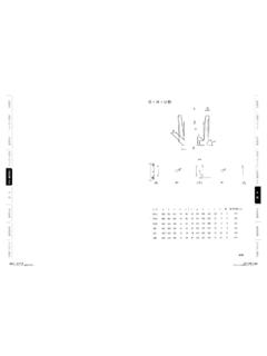
8 B= Socket Connector less sockets (with intent to use non-std socket contacts)Polarization (Keying)N= Normal (Included in part number)A, B, C, D,or EModification (applies to Aero part numbers only)01= Less contacts (is not marked on the part)340= Connector kitted with M85049/14-XXX341= Connector kitted with M85049/38-XXX straight clamp342= Connector kitted with M85049/39-XXX right angle clampConsult factory for other DTL 38999 S IIID38999/20 Wall Mounting ReceptacleAE320 Triple Start Threaded Coupling, Crimp Removable, Rear Release, Scoop-Proof BLUE COLOR BAND(REAR RELEASE)B4 MINOR KEYWAYSECDLOCKING INDICATOR BANDCOLOR: RED FMATING THREADMASTER ( ) (.085) MAXGROMMET EXTENSIONJ NUMBER OF TEETHK ACCESSORY (.280)MIN FULL THREADH MAXA[ LMAXGROMMETPage 38 Completed Part NumberPage 44 Contacts, Sealing Plugs and ToolsPages 17 19 Insert ArrangementsPage 37 Performance SpecificationsPages 15, 16 Insert Availability and Contact InformationPage 42 PolarizationNote 1: K Accessory Thread for AE320 is same as AE326( D Accessory Thread) on page 2: F Mating Thread for AE320 is same as AE326( E Mating Thread) on page 41 except it is Class 3:Maximum Grommet Extension for insert layoutsincorporating size 8 and 10 contacts = (.)]
9 234).ShellSizeABCDEGHJ LNo. of .012 .30(TP)(TP) .008 .20 .008 .20 MaximumMaximumTeethMaximuminchmminch mminch mminch mminch mminch mminch mminch DTL 38999 S IIID38999/24 Jam Nut ReceptacleAE324 Triple Start Threaded Coupling, Crimp Removable, Rear Release, Scoop-Proof "O" RING SEALHEX NUTPER D38999/28 MASTER KEYWAY4 MINOR KEYWAYSBFLATAE MATING THREADCJ THREADLOCKING INDICATOR BANDCOLOR: ( )MAXPANEL (.126) (.062)K ACCESSORY THREADF NUMBER OF TEETH[ (.085) MAXGROMMET EXTENSIONBLUE COLOR BAND(REAR RELEASE)GDPage 38 Completed Part NumberPage 44 Contacts, Sealing Plugs and ToolsPages 17 19 Insert ArrangementsPage 37 Performance SpecificationsPages 15, 16 Insert Availability and Contact InformationPage 42 PolarizationNote 1: K Accessory Thread for AE324 is same as AE326( D Accessory Thread) on page 2: E Mating Thread for AE324 is same as AE326( E Mating Thread) on page 41 except it is Class 3:Maximum Grommet Extension for insert layoutsincorporating size 8 and 10 contacts = (.]
10 234).ShellSizeABCDFG HJ+.004+.10+.024+.60No. of+.035+.90 Jam Nut .016 . DTL 38999 S IIID38999/26 Self-Locking, RFI Grounding PlugAE326 Triple Start Threaded Coupling, Crimp Removable, Rear Release, Scoop-Proof MASTER KEYRFI STRIP4 MINOR KEYSEMATING THREADBLUE COLOR BANDLOCATION OPTIONAL(REAR RELEASE) ( )MAXD ACCESSORY THREADT NUMBER OF (.085) MAX GROMMET (.280)MIN FULL THREAD[ AMAXCOUPLING NUT[ BMAX GROMMETNote :Maximum Grommet Extension for insert layoutsincorporating size 8 and 10 contacts = (.234).Page 38 Completed Part NumberPage 44 Contacts, Sealing Plugs and ToolsPages 17 19 Insert ArrangementsPage 37 Performance SpecificationsPages 15, 16 Insert Availability and Contact InformationPage 42 PolarizationShellSize A B DETA ccessory ThreadMating ThreadNo. of MaximumMaximumMetricClass DTL 38999 S IIIMIL-DTL- 38999 PolarizationSeries IIIK eying Positions C B D A MASTER KEYWAY NORMALN otes:1.]]