Transcription of MIL-DTL-5015 Style Circular Connectors
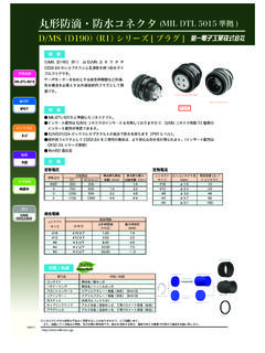
1 MIL-DTL- 5015 Style Circular Connectors D/MS A/B Series OUTLINE. D/MS A/B series is compatible with MIL-DTL- 5015 and Conforming a soldering termination connector. Standard A various combination of the plugs, receptacles and MIL-DTL- 5015 . accessories is also available and can be used for cable- to -cable usage and cable-to-panel usage. D/MS A/B series is provided with 12 kinds of shell sizes from 10SL to 36, 5 kinds of contact size from #16 to #0. and 73 kinds of insert arrangements to accommodate a wide variety of applications. APPLICATIONS. Aerospace, Machine Tool, Measurement Equipment, Communication Equipment and Other Industrial Equipment CONFORMING STANDARD. MIL-DTL- 5015 Class A and B. SAFETY STANDARD. UL, C-UL Approved: File Number E72124. Barrier FEATURES. Lock Type Threaded The barriers are placed between each contact on the insert to extend the creepage Coupling distance for the improvement of dielectric withstanding voltage characteristic.
2 Each of the plug shells and the receptacle shells can apply to both of the pin insert assemblies and the socket insert assemblies respectively excluding shell size 10SL. A combination of the sockets for input and pin for output is recommended since D/MS A/B series is often used for high voltage equipment to prevent from any accidents. The plug shell has a key way and the receptacle shell has a key. The key will be inserted into the key way before the contacts are mated. The insert is rotated within the shell from standard key way and 4 kinds of alternate insert positions, W, X, Y and Z are available to avoid cross plugging problem in applications requiring the use of more than one connector of the same size and arrangement. The solder cups in the insert assembly face in same direction to solder cables easier. The surface of shells is coated with zinc plating and finished with trivalent chromium treatment(*) in color black to conform to RoHS directives.
3 (* : Cadmium plating and Olive Drab color is MIL- DTL- 5015 specification). The conventional DMS series in Olive Drab color is also available upon your request. DDK Other Manufacture's Specifications and/or dimensions in this catalog are subject to change without notice. Your checking the latest specifications with our drawings would be highly appreciated. 161004. D/MS A/B Series SPECIFICATIONS. Rated Current Contact Size Assembled in Insulator 16 13A max. 12 23A max. 8 46A max. 4 80A max. 0 150A max. Rated Voltage Service Rating DC AC( ). INST 250V 200V. A 700V 500V. D 1,250V 900V. E 1,750V 1,250V. Dielectric Withstanding Service Rating Dielectric Withstanding Voltage at 1minute Voltage INST 1,000V AC( ). A 2,000V AC( ). D 2,800V AC( ). E 3,500V AC( ). Insulation 5000M min. at 500V DC. Resistance Contact Contact Size Test Current Voltage Descent Resistance 16 13A 87mV max.
4 12 23A 77mV max. 8 46A 80mV max. 4 80A 70mV max. 0 150A 65mV max. Operating -55 +125 . Temperature Applicable Applicable Cable Size Cable Size Contact Size Official Sectional Area Conductor Diameter 16 #16 22 Max. 12 #12 #14 Max. 8 #8 #10 Max. 4 #4 #6 Max. 0 #0 #2 Max. MATERIAL / FINISH. Item Material / Finish RoHS. Contact Copper Alloy / Silver or Gold Plating Compliant Compliant Insert Diallyl Phthalate Resin(Blue). Shell Aluminum Alloy / Zinc Plating, Black Trivalent Chromium Treatment Retaining Ring Copper Alloy / Nickel Plating Gasket Synthetic Rubber (Nitrile). Specifications and/or dimensions in this catalog are subject to change without notice. Your checking the latest specifications with our drawings would be highly appreciated. 2. D/MS A/B Series D/MS Series A/B Type Ordering Information D/MS3 1 0 2 A1 8 -1 0 P Y ( 6 2 ). Deviation Omit : Silver Plated Contacts (Standard).
5 (62) : Gold Plated Contacts ( m AU over Ni). Connector Style D/MS3100A Alternate Insert Position Wall Mount Receptacle No letter is required for normal position. The alternate insert positions, W, X, Y and Z, are available. W, X, Y and Z designate that an insert is rotated in its shell from the standard position. For detailed alternate insert positions, refer to page 8. C . 12S 36 Size). D/MS3101A. Cable Receptacle .. 12S 36 Size . D/MS3102A Contact Type Box Mount Receptacle Pin Contact S Socket Contact When a receptacle connector has pin contacts (P), its mating plug connector should have socket contacts(S). Reverse Style of contacts is also feasible. Shell Size Insert Arrangement 10SL 36 Size . Shell sizes are designated by the This is the number allocated to each shell size D/MS3106A respectively with its sequential number beginning from screw size of mating part which is Straight Plug number one(1).
6 (However, there are the numbers described in inches multiply by 16. which are not used.) The insert arrangement number ( ) When the screw size of mating does not show the number of contacts. part is 1 1/8-18, it is 1 1/8 X 16 =18 For example on the insert arrangement 18-10: of which shell size is 18. 18 shows the shell size. 10 shows the insert arrangement. (The number of contacts is 4.). (Available shell size) : With regard to the insert arrangement, refer to page 10SL,12S,14S,16S, 16, 18, 20, 22, 4 to page 7. 24, 28, 32 and 36. 10SL 36 Size . D/MS3106B. Straight Plug (Split Backshell). 12S 36 Size . D/MS3108B. Right Angle Plug (Split Backshell). 12S 36 Size . Specifications and/or dimensions in this catalog are subject to change without notice. Your checking the latest specifications with our drawings would be highly appreciated. 3. D/MS A/B Series Insert Arrangement List Front View of Pin Contact Number of Contact 1 2.
7 A. Insert B . B.. Arrangement A. B . B A. B . B A .. B A A.. B B B . B B.. Insert Number 20-2 10SL-4 12S-3 14S-9 20-23 32-5.. Contact Size 1-#0 2-#16 2-#16 2-#16 2-#8 A. 2-#0. A.. Service Rating D A A A A D. C A.. C B C B . B A A .. Rated Current 150A 13A 13A 13 ACB 46A 150A. A A AA.. B B A AA. B . B B A A.. A BB .. C B BC B B . B C A. B BB. B A B . C AB C. B . A C A A A. A. C A .. C A. Number of Contact 3. C B . C B. B .. C B B C CB B. C B . B.. A.. A. Insert . A. A . B . A A. Arrangement A A A A . B A A A . A A A C C A A C B . AA B A AA .. B C C A A .. C AA AA.. C . AB.. C C B B A B C C. B CBB B . B B C A CA C BA B. C C B B B.. C B B CC BB. C BB C BB B .. C . B C B . A B .. C B A C B. A .. C B . Insert Number 10SL-3 14S-1 14S-7 16S-5 16-10 18-5 18-21. C B.. C C B B.. C B.. Contact Size 3-#16 C 3-#16. C B B. 3-#16 3-#16 3-#12 2-#12 1-#16 3-#12.
8 Service Rating A A.. A.. A A.. D A. D A D A A A. A A. A. #12 : 23A. A AA.. C A A.. Rated Current . 13A 13A 13A 13A 23A 23A. C B . A A . A. D A A D A A. C B A .. #16 : 13A. A A C B C A C B . A B C A A. AA . A C A. D. A D. C B A C B . B C B. C B . C B. B C B. C B C C B B. A .. C B B C C B B .. D D C. C B .. C B . A C BB . Number of DContact 3. D A C B . DC . C. A .. C C B B D AB B. A . CC BB. C B C B. C B . C C. B B . CB B . C . A. D A A. D. A. Insert D A A A. A A. D A .. D . D A A D DA D A. Arrangement D. A A . A D. A D A D D . A A . A DD AA D A.. DD . A AA D C.. C B BA B. C B D A . D A . C B. C C B.. D C BA B D A . C B B A . A. C B C C B. CC BB C C B B C D C B. D A .. D A C . B . CC BB D . C B. C B C D B AC B D B . C B C B . D D A A C B . C B C B C B.. C. C B C B B. Insert Number 18-22 22-2 28-6 36-4. C B C C B B B B. C B . C.. C C. Contact Size 3-#16 3-#8 3-#4 3-#0.
9 A A. D(A) A.. D A D A A. Service RatingD.. D D D AA. D A A .. D. A(BC). D D A A D A . DD D A AAA D A D D . D D A D . A DD. C B D D A A D A D . D D A A A D.. C B . DD AA . Rated Current C. C. B 13A. B.. D.. 46A. A. 80A C B. 150A.. C B C B .. C B C B B . C C B B C B B. C C B B C C B B B B. CC BB CC BB BB. C C. C B C B B.. C C. CC. C. Contact Size Symbol A. #16D #12 #8 #4 #0. D A. A. A. A. Service Rating INST A D D E. D A D A . D A D. D A. Rated Voltage AC( ) 200 500 900 1,250. D A D. D A. D A. C B C B Rated Voltage DC 250 700 1,200 1,750. B. C. C. B. B C. C. B. B.. Contact Size .. #16 C #12 #8 #4. B. B #0. MAX Current 13 23 46C 80 150. B. /Contact . C B C B .. C. C. Specifications and/or dimensions in this catalog are subject to change without notice. Your checking the latest specifications with our drawings would be highly appreciated. 4. A A.
10 A C A A.. C A.. C B C B. B. C A B C A B. B . C A A.. A. A. C B D AA . C B. B A.. A . A . D/MS A/B Series A. A C B .. A.. C B. C B. Insert Arrangement List C B. C B. C B . C B C B. C B . C B. C B. A. A.. Number of Contact A.. 4 A. A.. A C B.. C B D A.. C B. Insert C B. D A. D A D A C B . D A . D . D A D A . D A DA A . Arrangement C B. D A D . C B A. C B C B . C B C B. C B C B C B. C B . C B C B . C B .. Insert Number 14S-2 18-4 18-10 20-4 22-10 22-22. D A . Contact Size 4-#16 4-#16 4-#12D 4-#12 4-#16 4-#8. D A . D A . A. Service Rating INST D A D E A. C B . D . C BA . C B D A . B A. C . Rated B CurrentD 13A 13A 23A 23A 13A 46A. A A. A A. C . D A D. D A C B A. D A D D. D A D. Number of Contact 4. D A D A. D A D. D A. D A. C B C B B. C B C B B B. C B C B B. C B C B . C. C B C B B. C C. A C.. A C. D A . D A D. Insert D A . D. A. D A. D A. Arrangement D.