Transcription of MILITARY & DEFENSE EDITION MD Series MIL-DTL-83513 …
1 MILITARY & DEFENSE EDITION Lightweight, High-Density Connectors Pre-Assembled Wire Harnesses PCB Angled & Straight ContactsMIL-DTL-83513 Micro-DMD SeriesMILITARY STYLE CONNECTORSCONNECTING YOUR ENGINEERING PASSIONRev. 2145Y- 1M I L N E C . C O MMDMD Series MIL-DTL-83513 Micro-D Style ConnectorsMilnec Interconnect SystemsHigh Reliability SimplifiedJust because your interconnect problem is complicated does not mean acquiring the solution has to be. Milnec connector systems and our all-in-one kits provide engi-neers the most complete and professional connector solutions with ease and technical clarity. Complete, high-reliability solutions Simple to understand technical data & configurations Online part builder tools, drawings, & documentation Field installable & serviceableHighest Manufacturing QualityWe invest in the finest equipment and modern production processes to ensure that our connectors will exceed your quality and performance expectations.
2 Our production processes include advanced computer numerical control machining, cosmetic and metal finishing, heat treatment, and stainless steel passivation. Traceability on 100% of the parts Quick production lead times Quantity support from R&D to production Just-in-time delivery, kitting, & special packaging Rapid tooling & prototyping for custom designsAbout Usilnec interconnect systems is a leader in the design, manufacture, and supply of high-performance cylindrical interconnect systems. From research stations in the Antarctic to spacecraft on the plains of Mars, our high-reliability connector systems conquer the most demanding environments. Milnec is a supplier to leading companies in 24 countries in the following industries: MILITARY & DEFENSE Aerospace & Space Railway & Mass Transit Industrial & Heavy Equipment Alternative Energy, Nuclear, Oil & GasLogistics Solutions for Global ApplicationsGlobal logistics and support means we deliver products on time every time to any destination.
3 To support your immediate requirements, we have extensive inventories, making most systems readily available for today s compressed design and production schedules. On average, custom connector solutions made to your exact configuration ship within seven days from the time of order placement. Worldwide shipping (restricted to NATO countries only) Web access to inventory, prices, & delivery information A large stock of popular parts for greater availability Competitive pricing and short lead times Impeccable customer service & technical supportHigh-Performance Cylindrical ConnectorsPerformance With Environmental ResponsibilityRoHS compliant products are available to support environmental responsibility and legislative conformity. Through simple modification codes, Milnec provides a wide variety of material options to easily provide customers with fully compliant and eco-friendly connector components.
4 RoHS compliant materials & finishes Simple material modification codes Lead-free solder contactsMilnec Interconnect Systems3947 West Lincoln Highway #192 Downingtown, PA 193351-855-4 MILNEC Toll MILITARY Cage Code: 6 STX5 NAICS Code: 423690 Milnec Interconnect Systems Rev. 2145M I L N E C . C O MY- 2 MDMD Series MIL-DTL-83513 Micro-D Style ConnectorsFeatures & BenefitsEnvironmental Protection With Ease MD Series Micro-D connectors are manufactured to withstand harsh environments. They are environmentally sealed when mated. The wire side of the connectors is protected by high-quality epoxy that encapsulates the contacts in the insulator, preventing any contact pullout. MIL-DTL-83513 Sub-Miniature PerformanceThe MD Series is Milnec s Micro-D solution for applications in which small, high-density connectors are required and standard D-Subminiature connectors are too large and too heavy.
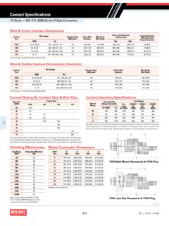
5 The MD Series meets and exceeds the MIL-DTL-83513 specification for performance and durability. MD connectors are manufactured with a strong yet lightweight aluminum shell and a variety of high-reliability, high-density contact configurations. The connectors are designed with size #24 contacts on .050 inch ( mm) centers and are typically half the size of standard D-Sub connectors. Milnec MD Series connectors are ready for the rigors of your next advanced interconnect of ContentsAbout Us ..Y- 1 Features & Benefits ..Y- 2 Series Specifications ..Y-3 Contact 7 Materials & 8(MDS1) Solder Cup 9(MDH1) Pre-Wired 11(MDP1) PCB 1 3(MDP2) Condensed PCB 1 5(MDP3) 90-Degree PCB Micro-D ..Y- 1 7(MDP4) Condensed 90-Degree PCB 1 9 Mounting Mounting Connector Layouts ..Y-23 PCB Contact Variety MD connectors can be built with PC tail contacts in either straight or 90-degree configurations.
6 Contacts are available in a variety of Connectors for Quick Assembly MD connectors are available in three styles: solder, printed circuit board (PCB or PC tail), and pre-wired. The pre-wired connectors come in a variety of wire lengths and types to meet the demands of modern interconnect applications. Solder connectors PC tail connectors Pre-wired connectorsRev. 2145Y- 3M I L N E C . C O MMDMD Series MIL-DTL-83513 Micro-D Style ConnectorsSeries SpecificationsEnvironmental Characteristics Operating Temperature Range -67 to +257 F (-55 to +125 C). Fluid Immersion Connectors shall meet mating force requirements following 20 hours immersion in synthetic lubricating oil and 1 hour immersion in coolanol 25 when tested in accordance with MIL-DTL-83513F paragraph Thermal Vacuum Outgassing The assembled connector mass excluding metallic parts shall not exceed total mass loss (TML) or total volatile condensible materials (CVCM) when tested in accordance with ASTM E595.
7 Salt Spray Rating See Materials & Finishes, p. Wired, mated connectors shall be subjected to humidity conditioning in accordance with EIA-364-31, Test Condition IV. After a minimum of 3 hours of step 7a of the final cycle, and while the connectors are still subjected to high humidity, the insulation resistance shall be measured when the chamber temperature reaches 68 F [ 5 F (20 C 5 C)]. Insulation resistance shall not be less than 100 megohms, and connectors shall pass a DWV test of 360 volts (RMS 60 Hertz AC). Endurance Characteristics Coupling Cycles Connectors shall be capable of 500 cycles of mating with no damage or degradation to electrical performance. Shock Connectors, when mated, wired in Series and fixtured in accordance with MIL-DTL-83513F, shall not exhibit any discontinuity longer than 1 microsecond when tested in accordance with EIA-364-27, Test Condition E, which specifies an amplitude of 50 g peak.
8 Connectors shall not be damaged and no loosening of parts shall occur. High-Impact Shock Per MIL-S-901, a 400 lbs (181 kg) hammer dropped onto assembly from a height of 1 ft (30 cm), 3 ft (91 cm), and 5 ft (152 cm) applied to connector assembly in 3 axes, totaling 9 impacts; connector assembly experienced less than 1 microsecond maximum discontinuity with no cracking, loosening of parts, or other failures. Thermal Shock Unmated connectors shall withstand 5 cycles of thermal shock with a minimum temperature of -85 F (-65 C) and a maximum temperature of 302 F (150 C) when tested in accordance with EIA-364-32, Condition IV. Connectors shall not exhibit any detrimental damage or degradation of electrical performance. Sine Vibration Connectors, when mated, wired in Series and fixtured in accordance with MIL-DTL-83513F, shall not exhibit any discontinuity longer than 1 microsecond when tested in accordance with EIA-364-28 Test Condition IV, which specifies 12 hour duration, 10 Hz to 2000 Hz, and amplitude of 20 g peak.
9 Connectors shall not be damaged and no loosening of parts shall Characteristics Contact Engagment and Separation Force Maximum engaging force shall be ounces when tested in accordance with EIA-364-37, except with a .0221 ( .0001) diameter sleeve with a 6-10 microfinish. Minimum separation force shall be ounces when tested in accordance with EIA-364-37, except with a .0230 ( .0001) diameter sleeve with a 6-10 microfinish. Connector Mating and Unmating Force The maximum mating and unmating force shall not exceed a value equal to 10 ounces times the number of contacts, when tested per EIA-364-13. Mate connectors three times before initial measurements are taken. Resistance to Soldering Heat Connectors with solder cup contacts shall not be damaged following soldering with a 680 F (360 C) solder iron for at least 4 seconds in accordance with EIA-364-56 Procedure 1.
10 Connectors with printed circuit board terminations shall withstand immersion in a solder bath for 9-11 seconds at 500 F (260 C) when tested in accordance with EIA-364-56 Procedure 3 Test Condition B. Connectors, after cooling, shall not exhibit damage or warpage when examined at 10X magnification. Solderability Solder cup and printed circuit terminals shall meet the solderability requirements of MIL-STD-202 Method 2145M I L N E C . C O MY- 4 MDMD Series MIL-DTL-83513 Micro-D Style ConnectorsSeries SpecificationsContact Characteristics Pin Contacts Beryllium copper, gold plated in accordance with ASTM B 488 Type II Class (50 Microinches Minimum) Code C, over nickel underplate in accordance with SAE-AMS-QQ-N-290, Class 2 (30 microinches minimum). Socket Contacts Phosphoric bronze in accordance with ASTM 139 gold plated in accordance with ASTM B 488 Type II Class (50 microinches minimum) Code C, over nickel underplate in accordance with SAE-AMS-QQ-N-290, Class 2, (50-150 microinches).