Transcription of MILLIMETER WAVE TESTS AND INSTRUMENTATION
1 MILLIMETER WAVE TESTS AND INSTRUMENTATIONM ohamed M. Sayed, Microwave and MILLIMETER Wave SolutionsSanta Rosa, CA 95404E-mail: Phone: (707) 318-5255 AbstractThe recent growth in MILLIMETER wave applications has created a corresponding demand formillimeter wave TESTS and INSTRUMENTATION . Network analyzers, signal analyzers, signalgenerators, power meters and noise figure analyzers will be discussed in this article. Optimumchoice of INSTRUMENTATION for specific applications will also be IntroductionMillimeter wave frequencies are between 30 and 300 GHz (wavelengths from 10 to 1 mm). MILLIMETER waves are attenuated by atmospheric constituents and gases at different rates fordifferent frequencies [1].
2 Frequencies where gaseous absorptions are at minimum are calledatmospheric windows. Regions of maximum absorption are called absorption bands. The mainmillimeter wave atmospheric windows are centered around 35, 94, 140 and 220 GHz, and themain absorption bands are around 60, 120 and 182 GHz. Figure 1 shows these windows main applications for MILLIMETER wave systems are in communications, homeland security,imaging, radar and spectroscopic observation. Most MILLIMETER wave applications employmillimeter wave measurement systems to verify device specifications. These measurementsystems utilize microwave INSTRUMENTATION and external up/down converters to perform therequired TESTS . This paper will present an overview of MILLIMETER wave TESTS and instrumentationacross the range of 30 to 325 MILLIMETER Wave ApplicationsTypical MILLIMETER wave applications are around atmospheric windows or absorption of these applications are: 1).
3 Satellite Communications at 60, 94, and 140 GHz, 2). Sci-entific research at 220 and 240 GHz, 3). Imaging and homeland security at 94 GHz, and 4). Au-tomotive radar at 77, 94, and 140 between MILLIMETER wave applications and measurement systems can be one of fourmethods: coaxial, waveguide, probe on wafer or antenna. Table A shows coaxial millimeterwave connectors [2].TABLE A: COAXIAL MILLIMTER WAVE CONNECTORSTypeOther NameMaximum FrequencyIn GHzUsable Frequency In , wave waveguide bands are shown in Table B. Current designation, band frequencyrange and waveguide inside dimensions in mils are also shown in Table B. Since waveguides aredesigned to work in the TE01 mode, each band has a cut off frequency as shown in Table this cut off frequency, MILLIMETER waves cannot propagate into the bandwidths are typically around 50%.
4 It is strongly recommended to work below theTE20 or twice the cut off frequency of waveguide B: WAVEGUIDE BANDS AND CHARACTERISTICSWG BandCurrentDesignationFrequencyin GHzCutoff Frequencyin GHzDimension in x x x x x x x x x x 17 Probes are designed to be attached to connectors from one side and wafers on the other C shows the popular coaxial probe frequency ranges [3].TABLE C: PROBE FREQUENCY RANGESP robe NumberConnector TypeFrequency mm 40 mm50 GHz3V 65 mm67 mm110 GHzThe connection between the wafer probe to the test system could be coaxial or probes that connect to waveguides cover only the waveguide bandwidth ( 75-110 GHz). At the present time probes are available commercially up to 220 GHz [4].
5 Antennas,receiving or transmitting, cover the application s bandwidth, 76-77 GHz, 60-61 GHz, or 94-95 GHz. Most applications consist of transmitters and receivers, only transmitters, or onlyreceivers. Information to be transmitted and/or received is usually contained in modulation of these techniques are AM, FM, Pulsed, Phase or FMCW. Measurement systems need toverify the output power, the modulation purity of the information, and the sensitivity of MILLIMETER Wave Test Parameters and SpecificationsTest parameters and specifications are strong functions of the specific application. However, thefollowing are basic specifications for most applications:1. Frequency: Transmit and/or Receive2.
6 Bandwidth: Transmit and/or Receive3. Modulation 4. Power Transmit (min/max), Receive (min/max)5. Distance/Resolution6. Antenna or Beam Width7. Update Rate8. Mechanical dimension and weight 9. Power Supply (voltage, current, and DC power consumption)10. Interface11. Cost12. Technology wave ranges can be divided into three regions. The first is 30-50 GHz which usuallyuses coaxial connectors and cables, and is considered by some users as a microwave region. Thesecond region is 50-110 GHz, and is crowded with commercial and non-commercialapplications. Activities in this region can be as high as 50% of the entire MILLIMETER wavespectrum. The third region is 110-325 GHz, constitutes 20% of all activities, and is growingrapidly over MILLIMETER wave applications have a very small bandwidth of < 1 GHz.
7 The modulationbandwidth is much smaller than the application bandwidth, usually 10-100 wave applications can be used in one of four modes: 1). CW mode, 2). ModulatedCW mode, 3). Pulsed RF mode, and 4). Pulsed RF and pulsed bias modes. The number of portscould vary from two ports to multiports (4, 5, ) and could be single ended or transmitted and/or received can be modulated in scalar or vector techniques. Millimeterwave measurements can be divided into three ranges: 1). In band, 2). Out of band, and 3). Inband harmonic. Table D shows a summary of MILLIMETER wave application D: MILLIMETER WAVE APPLICATION PARAMETERSF requencyRFMWMMWMMW (GHz)30-5050-110110-325 Application BWNarrow BandWide BandUltra Wide BandModulation BWNarrow BandWide BandPowerLowNormalHighConnectionsCoaxial WGProbeType of MeasurementIn bandOut of bandHarmonicDUT2 PSE2 PDMPDS ignal ModeCWRFP ulsed RFPRF/PBSignal SourceScalar (AM, FM, P, P)Vector4.
8 MILLIMETER Wave InstrumentationMeasurement systems are determined by types of MILLIMETER wave applications andspecifications. However, most systems consist of four instruments: signal generators (scalar orvector), signal analyzers (scalar or vector), network analyzers (scalar or vector) and powermeters. For specific applications, noise figure analyzers and/or phase noise systems are Signal GeneratorsMillimeter wave signal generators with full waveguide coverage are key factors in millimeterwave applications. Most MILLIMETER wave users already own microwave signal generators andwant to extend present microwave measurement capabilities up to 325 GHz [5].Two ways to generate MILLIMETER wave signals are up converting or multiplying.
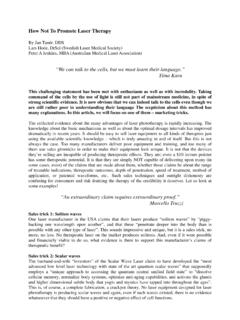
9 For scalarmodulation and measurements, multiplying the output of microwave signal generators will beoptimum. For example, multiplying by 6 using the range of 10-20 GHz will deliver thefrequency range of 75-110 GHz in the WR-10 waveguide band. However, an up converter isrequired for vector modulation to keep the relative phase in control at MILLIMETER wavefrequencies. Typical output powers are: +13 dBm for 33-50 GHz, +10 dBm for 50-75 GHz, +7dBm for 75-110 GHz, zero dBm for 110-170 GHz, -10 dBm for 140-220 GHz, and -20 dBm for220-325 GHz. New techniques are in progress to generate MILLIMETER wave signals from photomixing. However, the output power is much lower than multiplying or up converting.
10 Figure 2shows a typical MILLIMETER wave signal generator. Research is in progress at the present time togenerate sub- MILLIMETER wave signals at 330-500 GHz in the waveguide band, and 500-750 GHz in the waveguide Generator20 GHz461218304250 75 GHz75 110 GHz140 220 GHz220 325 GHz330 500 GHz500 750 GHzFigure 2: Typical MILLIMETER Wave Signal Signal AnalyzersFor scalar analysis measurements, harmonic mixers are used to down convert the millimeterwave signal into the IF of microwave signal analyzers. Table E shows the IF and LO frequenciesof signal analyzer manufacturers A G [6]. The signal analyzer s firmware determines theharmonic number and displays the correct spectrum. Figure 3 shows a typical MILLIMETER wavesignal analyzer.