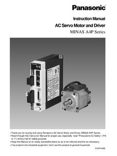
Transcription of MINAS A-series Operating Manual - Panasonic
1 AC Servo Motor DriverMINAS A-seriesOperating Manual Thank you very much for your buying Panasonic AC Servo Motor Driver, A-series . Before use, read through this Manual to ensure proper use. Keep this Manual at an easilyaccessible place so as to be referred anytime as sure give this instruction Manual to the of Contents- 2 -Safety Precautions 4 Introduction 8 After Opening the Package 8 Check the Model of Driver 8 Check the Model of Motor 9 Check the Combination of Driver and Motor 10 System Configuration and wiring 18 System Configuration and wiring 18 general wiring DiagramList of Available Components 20 Main Circuits 22 CN SIG Connector(For Encoder) 24 CN SER and CN NET Connectors(For PC or Controller) 27 CN I/F Connector(For Controller) 28(Circuits Available for Typical Control Modes) 29(Input and Output Signals, and their Functions)
2 32(Interface circuit) 38 Parameter Setting 42 Overview 42 ParAmeter Groups and Listing 42 Setting the Parameters 47 MODEs Structure 48 Before UsePreparationsand AdjustmentsParts Description 12 Driver 12 Motor 13 Installation 14 Driver 14 Motor 16 Trial Operation 50 Inspections before Trial Operation 50peration WithoutMotor Load (JOG) 51 Operation With CN I/F Connected 52 Adjustments 55 Purposes of Gain Adjustments 55 Kinds of Gain Adjustments 55 How to Adjust Gain 57 How to Use "NormalAuto-Gain" Tuning 58 How to Use "Real TimeAuto-Gain" Tuning 59 How to Adjust Gain Manually 60 Protective Functions 64 Maintenance andInspections 71 Conformance to EC Directives and UL Standards App.
3 2 List of Connectable Motors App. 7 How to UseApp App. 9"Absolute" Driver App. 20"Full Close" Driver App. 28 Details of Parameters App. 30 Details of Operation App. 57 AppendixesImportant InformationTroubleshooting 73 After-Sale Service Back coverOverview of a Communication Control Software PANATERM App. 67 Optional Parts App. 69 Recommended Parts App. 84 Outer Views and Dimensions App. 86 Properties App. 106 Specifications App. 107- 4 -DANGERS afety PrecautionsObserve the following precautions in order to avoid injuries of operators andother persons, and mechanical following DANGER and CAUTION symbols are used according to the level of dangers possibly occur-ring if you fail to observe the instructions or precautions following symbols indicate what you are not allowed to do, or what you mustobserve.
4 (Important)DANGERCAUTIONI ndicates a potentially hazardous situation which, if not avoided,will result in death or serious a potentially hazardous situation which, if not avoided, will result inminor or moderate injury and physical symbol indicates that the operation is symbol indicates that the operation must be per-formed without 't insert your hands in to observe thisinstruction could result inburns and/or electric over-current protection, earthleakage breaker, over-temperatureprotection and emergency stopshould to observe thisinstruction could result in elec-tric shocks, injuries 5 -DANGERG round the earth terminal ofthe to observe thisinstruction could result inelectric 't touch the rotating part of themotor in to observe this instruction couldresult in partDo not expose the cables tosharp edges, excessive pressingforces, heavy loads or to observe thisinstruction could result inelectric shocks,malfunction the transportation, wiringand inspection at least 10minutes after the power to observe this in-struction could result inelectric 't subject the product to wa-ter splash, corrosive gases, flam-mable gases and to observe this in-struction could result UseInstall an external emergencystop device so that you canshut off the power in anyemergency to observe thisinstruction could result ininjuries, electric shocks, fire,malfunction and/or 6 -CautionSafety PrecautionsUse the motor and driver inthe specified to observe this in-struction could result in the trialoperations with themotor fixed but without motor loadconnected.
5 Connecting a load to themotor is possible only aftersuccessful trial to observe this in-struction could result in extreme adjustment orchange. Avoid an operationwhich causes to observe thisinstruction could result an error occurs, remove thecauses for the errora andsecure the safety beforerestarting the to observe thisinstruction could result 't touch the motor, driveror its regenerative dischargeresistor, since they to observe thisinstruction could result 't modify, dismantle orrepair the to observe this in-struction could result inelectric shocks and/or inju-ries.(Important)- 7 -Caution*Provide appropriate settings as a preparedness againstthe accidental restart of the machine in order to ensurethe safety of recovery from the powerfailure, the equipment mayrestart suddenly. Don't approachto the equipmentduring power the voltage to observe thisinstruction could result inelectric shocks,injuries and/or equipment should be treatedas an industrial waste when it isdisposed discarding batteries,insulate them with tapes orother similar means and obeythe local 't block the heatdissipation hole or insertforeign matters in to observe thisinstruction could resultin electric shocks,injuries and/or sure that thewirings are to observe thisinstruction could result inelectric shocks, 't hold the cables ormotor shaft when transpotingthe to observe thisinstruction could resultin Use- 8 -MSDA043A1 AUU1~35~611~12478910 IntroductionAfter Opening the Package After Opening the Package Make sure that the product is what you have the Model of DriverName plateModel DesignationSeries symbolA.
6 A-seriesRated motor output (seeTable 1-a)Check whether the product has been damaged or not during the product is not correct, or it has been damaged, contact dealer or sales 32V 17bits1 3 30W50/60Hz 0~ OUTPUT ENCODERAC SERVO DRIVER60/75 Wire OnlyUse Copper Conductors OnlyRefer to Manual for wiring and Wire SizeRefer to Manual for Over Load input voltageRated motor outputNumber of pulses of theencoder(resolution)Rated output currentSerial NumberCustomspecificationCustom specification 2(A, B, )Custom specification 1 (1,2, )Rotary encoder (see Table 1-b)Power supply1: Single-phase, 100V3: Three-phase, 200 VApplicable motorsSymbolMSDMDDMHDMFDMQDMGDA pplicable motorsMSM Low inertiaMDM Middle inertiaMHM High inertiaMFM FlatMQM Flat & smallMGM Middle inertia- 9 -MSMA042A1 AUU1~35~611~12478910 Check the Model of MotorName plateTypeSerial NoRevolution ratingModel DesignationRated output (see Table 1-a)Motor structure(see Table 1-c)AC SERVO MOTORRATINGS1 MODELMSMA022A1 AINS.
7 CLASS B (T V) A (UL)CONT. OUTPUTRATED 3 AC92IP65 VMatsushitaElectric Industrial in JapanRated outputSeries symbolA: A-seriesVoltage1: 100V2: 200VZ: 100/200 VRotary encoder (see Table 1-b)Custom specification1: StandardCustomspecificationSymbolMSMMDMM HMMFMMQMMGMTypeLow inertiaMiddle inertiaHigh inertia Flat Flat & smallMiddle inertiaSymbolACDTypeIncrementalAbsoluteA bsolute/incrementalNo. of pulses2500P/rLead wire11-wire7-wire7-wireSpecificationsRes olution1000017bit17bitBefore UseSymbol3A5A0102030405060809 Rated output30W50W100W200W300W400W500W600W750W 900 WSymbol10121520253035404550 Rated 1-aRated Motor OutputTable 1-bRotary Encoder- 10 -Motor StructureTable 1-cIntroductionCheck the Combination of Driver and MotorThe driver has been designed for use in combination with the specified motors only. Checkthe specifications (Series symbol, output rating, voltage rating and encoder type) of the mo-tor you want to (Small)Low inertiaMSMA(Large)Low inertiaMotor typeMSMA3 AZA**MSMA5 AZA**MSMA011A**MSMA021A**MSMA041A**MSMA3 AZA**MSMA5 AZA**MSMA012A**MSMA022A**MSMA042A**MSMA0 82A**MSMA102A**MSMA152A**MSMA202A**MSMA2 52A**MSMA302A**MSMA352A**MSMA402A**MSMA4 52A**MSMA502A** typeIncremental2500P/r, 11wiresIncremental2500P/r, 11wires"D-cut" shafts are availablefor MSMA30W to 750 Wand MQMA100W to sealNoneStraightABCDS haftBrakeNoneYesNoneYesD-cutNPQRKey wayEFGNoneWith the incremental type encoder: 2500P/r- 11 -< Notes >1.
8 The above table shows the possible combinations between the driver (MSDA) and low-inertia type motors (MSMA). For middle-inertia (MDMA), high-inertia (MHMA), flat (MFMA),flat & small (MQMA) and middle-inertia (MGMA) motors, see the The default is for "incremental" spec. When you use the driver with the "absolute" spec, you need to; 1) Change the value of the parameter "Absolute encoder set-up (PrOB)" from 1 (factoryset default) to 0. 2) Install the battery (see Appendix "Optional Parts" for the batteries).3. The absolute/incremental spec driver can be used as "Full Closed Driver".With the absolute/incremental type encoder, 17 bitsMotorAmplifierMSDA3A1D1 AMSDA5A1D1 AMSDA011D1 AMSDA021D1 AMSDA041D1 AMSDA3A3D1 AMSDA5A3D1 AMSDA013D1 AMSDA023D1 AMSDA043D1 AMSDA083D1 AMSDA103D1 AMSDA153D1 AMSDA203D1 AMSDA253D1 AMSDA303D1 AMSDA353D1 AMSDA403D1 AMSDA453D1 AMSDA503D1 AMotor typeMSMA3 AZC**MSMA5 AZC**MSMA011C**MSMA021C**MSMA041C**MSMA3 AZC**MSMA5 AZC**MSMA012C**MSMA022C**MSMA042C**MSMA0 82C**MSMA102D**MSMA152D**MSMA202D**MSMA2 52D**MSMA302D**MSMA352D**MSMA402D**MSMA4 52D**MSMA502D** typeWith the absolute/incremental typeencoder, 17 bitsAbsolute/incremental type,17 bits, 7 wiresSee Note 2)Before UseSeriessymbolMSMA(Small)Low inertiaMSMA(Large)Low inertiaAmplifiertypeType1 Type2 Type2 Type1 Type2 Type2 Type4-2 Type4-3 Type5- 12 -Parts DescriptionDriver< Notes >For detailed information for each of driver types, see the drawings in the Appendix.
9 Safe separation are provided between power board and control : MSDA023A1A (200V 200W: Type 1) mTerminal block cover opened n200V 200W023A1 AMSDAWVUSIGI/FSERNETWVUSIGI/FSERNETSETMO DEGSPIMIDL1L2L3rtPB1B2 SETMODEGSPIMIDCAUTIONC onnect thewiring correctlyand properly,and screw thecover afterwire connectionRotary switch (ID)Mounting bracketLED indicator(6 digits)Communication connector 1 (CN NET)Communication connector 2 (CN SER)MODE selector switchControllerconnection(CN I/F)Encoderconnection(CN SIG)Data settingbuttons: SHIFT: UP: DOWN Check pinsMains powerconnectionControl powerconnectionExternal regenerativedischarge resistorconnection Earth connections (2)Terminalblock coverMotor connection ( )TerminalSET buttonCover securing screw mTerminal block cover closed n- 13 -< Notes >For detailed information for each of motor types, see the drawings in the : Small Low-Inertia Motor (MSMA Series, 750W and below)Mounting bolt holes (4)FlangeFrameMotor cableEncoderEncoder cableBefore UseBrake cable- 14 -InstallationThe driver and motor should be properly installed to avoid failures, mechanical damages and Indoors, where the driver is not subjected to rain water and direct sun beams.
10 Note thatthe driver is not a waterproof A void the place where the driver is subjected to corrosive gases, flammable gases,grinding liquids, oil mists, iron powders and cutting Place in a well-ventilated, and humid- and dust-free Place in a vibration-free ConditionsHow to InstallAhis is a rack-mount type. Place the driver vertically. Allow enough space surrounding for ventilation. Type 3 and smaller (up to 750W): Back panel mount type (projected, use Bracket A) Type 4 and larger (1kW and larger): Front panel mount type (recessed, use Bracket B)Bracket AMSDA 750 Wand smallerBracket BMSDA 1kWand largerB If you want to change the mounting configuration, use the optional bracket (see Appendix"Optional Parts").C Fit to noncombustibles such as metal.(Types 1 to 3)ItemAmbient temperatureAmbient humidityStorage temperatureStorage humidityVibrationAltitudeConditions0 to 55 C (free from freezing)Not greater than 90%RH (free from condensation)-20 to 80 C (free from condensation)Not greater than 90%RH (free from condensation)Not greater than ( ) at 10 to 60 HzNot greater than 1000 m(Types 4-2 - 4-3,Type 5)- 15 -ID MODEIMI/FSIGUVWSPGSETID MODEIMI/FSIGUVWSPGSETID MODEIMI/FSIGUVWSPGSETID MODEIMI/FSIGUVWSPGSETM ounting Direction and Space Requirements Allow enough space to ensure enough cooling.