Transcription of Minia LFE Residual current circuit breakers - OEZ
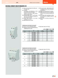
1 Minia LFE Residual current circuit breakers Residual current circuit breakers LFE. Residual current circuit breakers with conditional short- Equipped with device status indicator. circuit current 6 kA. Wide range of accessories - auxiliary and signal switch- They react to sine-wave Residual current (type AC). es, undervoltage releases and shunt trips, intercon- For protection: necting busbars etc. against dangerous contact with live parts (I n 30 mA) Possibility of locking and sealing in off or on position. against dangerous contact with dead parts Possibility of interconnection with circuit breakers LTE, against fire or short- circuit in reduced insulation capacity LTN by means of interconnecting busbars up or down. of electrical equipment (I n 300 mA). N-pole of Residual current circuit breakers in switching Mounting/dismantling on/from U rails: The latches on it closes before and in switching off it opens after enable very quick mounting and dismantling by the other poles.
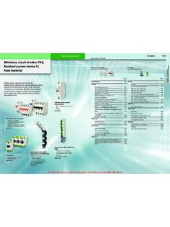
2 Hand, without any tool needed. Residual current circuit breaker are testing once per Operating ambient temperature is for all designs 6 months. already from -25 C to +45 C. Residual current circuit breakers 2-pole, type AC. Standard type for common use in building and housing Surge current resistance 250 A (8/20 s). installations up to 40 A, AC 230 V. 6 000 -25. I n In Type Order Number Weight Package [mA] [A] code of modules [kg] [pcs]. 10 16 LFE-16-2-010AC OEZ:42388 2 1. 25 LFE-25-2-030AC OEZ:42389 2 1. 30. 40 LFE-40-2-030AC OEZ:42390 2 1. 25 LFE-25-2-100AC OEZ:42391 2 1. 100. 40 LFE-40-2-100AC OEZ:42392 2 1. 25 LFE-25-2-300AC OEZ:42393 2 1. 300. LFE-25-2-030AC 40 LFE-40-2-300AC OEZ:42394 2 1. Residual current circuit breakers 4-pole, type AC. Standard type for common use in building and housing Surge current resistance 250 A (8/20 s). installations up to 80 A, AC 230/400 V. 6 000 -25. I n In Type Order Number Weight Package [mA] [A] code of modules [kg] [pcs].
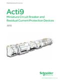
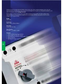
3 25 LFE-25-4-030AC OEZ:42395 4 1. 40 LFE-40-4-030AC OEZ:42396 4 1. 30. 63 LFE-63-4-030AC OEZ:42397 4 1. 80 LFE-80-4-030AC OEZ:42398 4 1. 25 LFE-25-4-100AC OEZ:42399 4 1. 100 40 LFE-40-4-100AC OEZ:42400 4 1. 63 LFE-63-4-100AC OEZ:42401 4 1. 25 LFE-25-4-300AC OEZ:42402 4 1. LFE-40-4-030AC. 40 LFE-40-4-300AC OEZ:42403 4 1. 300. 63 LFE-63-4-300AC OEZ:42404 4 1. 80 LFE-80-4-300AC OEZ:42405 4 1. 40 LFE-40-4-500AC OEZ:42406 4 1. 500. 63 LFE-63-4-500AC OEZ:42407 4 1. S2L. Accessories Auxiliary and signal switches PS-LT, SS-LT page B36. Shunt trips SV-LT page B37. AS-50-S-AL01 Undervoltage releases SP-LT page B37. Locking inserts OD-LT-VU02 page B39. Interconnecting busbars S2L, S2L+N, S3L+N, ), S4L page B45. Terminal extension AS-50-S-AL01 page B47. 1). For interconnection of the Residual current circuit breaker with a series of circuit breakers where the series of circuit breakers needs to start from N-pole of the Residual current circuit breaker . OD-LT-VP01. SV-LT PS-LT.
4 C4. LFE Residual current circuit breakers Minia Residual current circuit breakers LFE. Specifications Type Standards EN 61008-1 EN 61008-1. EN 61008-2-1 EN 61008-2-1. EN 61543 EN 61543. Approval marks Number of poles 2 4. Type AC AC. Rated current In 16, 25, 40 A 25, 40, 63, 80 A. Rated Residual current I n 10, 30, 100, 300 mA 30, 100, 300, 500 mA. Rated operating voltage Ue AC 230 V AC 230/400 V. Min. operating voltage Umin for I n = 30 mA AC 195 V AC 195 V. (for test button function) Umin for I n 30 mA AC 100 V AC 100 V. Max. operating voltage Umax AC 250 V AC 250/440 V. Rated frequency fn 50 Hz 50 Hz Rated conditional short- circuit current Inc 6 kA (see table below) 6 kA (see table below). Rated making and breaking capacity Im 500 A 800 A. Surge resistance 250 A 250 A. Mechanical endurance > 10 000 operating cycles > 10 000 operating cycles Electrical endurance > 10 000 operating cycles > 10 000 operating cycles Degree of protection - with connected conductors IP20 IP20.
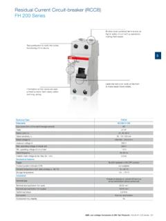
5 Mounting on U rail according to EN 60715 type TH 35 TH 35. Connection Conductor Cu - rigid (solid, stranded) 1) 35 mm2 35 mm2. Conductor Cu - exible 1) 25 mm2 25 mm2. Screw head type PZ2 PZ2. Torque 3 Nm 3 Nm Top or bottom connection top/bottom top/bottom Operating conditions Ambient temperature -25 +45 C -25 +45 C. Working position arbitrary arbitrary Climatic resistance (EN 60068-2-30) 28 operating cycles 28 operating cycles (55 C, 95 % relative air humidity) (55 C, 95 % relative air humidity). 1). For detailed connection of conductors see table on page C6. Protection of Residual current circuit breakers A) Short- circuit protection B) Protection against overload In function principle, Residual current circuit breaker is not possible to use for short- circuit protec- Protection of the Residual current circuit breakers against overload may be provided by fuses or tion. For circuit protection it is necessary to use a fuse or a circuit breaker , that cuts the short-cir- circuit breakers subject to following conditions: cuited circuit safely off.
6 The Residual current circuit breaker must only withstand the through-going - rated current of the fuse-link must be by one degree lower than rated current of the short- circuit current . The amplitude of the maximum through short- circuit current is defined as Residual current circuit breaker In of the fuse by one degree lower In of the Residual current circuit breaker rated conditional short- circuit current Inc. The table below indicates the rated conditional short- - rated current of the circuit breaker must be equal or lower than the rated current of the circuit current depending on the max. backup fuse and the circuit breaker . Residual current circuit breaker In of the circuit breaker In of the Residual current circuit breaker . Rated conditional short- circuit current with backup fuse Design Rated current In Max. backup Rated conditional short- circuit current LFE [A] fuse gG Inc [kA]. 2-pole 16 40 63 A 6 kA. 25 40 80 A 6 kA. 4-pole 63 80 100 A 6 kA. Rated conditional short- circuit current with backup circuit breaker Residual current Backup circuit breaker Rated conditional short- circuit current circuit breaker Type In of the circuit breaker Inc [kA].
7 LFE LTP, LTK , LTS, LVN In MCB In RCCB 6 kA. Powers losses P. Design Rated Rated Residual current I n [mA]. LFN current In 10 30 100 300 500. [A] AC AC AC AC AC. 16 W/pole - - - - 2-pole 25 - W/pole W/pole W/pole - 40 - W/pole W/pole W/pole - 25 - W/pole W/pole W/pole - 40 - W/pole W/pole W/pole W/pole 4-pole 63 - W/pole W/pole W/pole W/pole 80 - W/pole - W/pole - C5. Minia LFE Residual current circuit breakers Residual current circuit breakers LFE. Connection range Number of connected conductors Rigid conductor (solid, stranded) Conductor exible with a sleeve Conductor exible without a sleeve 1). 2 2. 1x conductor 1x ( 35) mm 1x ( 25) mm 1x (1 35) mm2. 2x conductor 2x ( 10) mm2 2x ( 4) mm2 2x (1 4) mm2. 1x conductor + interconnecting busbar 1x (10 25) mm2 + interconnecting busbar 1x (6 16) mm2 2) + interconnecting busbar - pin thickness max. mm pin thickness max. mm 1). The conductor must be twisted before insertion to a terminal; individual conductor fibres must not stick out of the terminal.
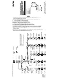
8 2). In case of use of a sleeve without plastic neck: conductor 1x (6 25) mm2. If more conductors are used they must be of the same type and cross-section. Dimensions 2 90. 64. Diagram 2 1 N 1 3 5 N. 2 N 2 4 6 N. Connection Standard zapojen . Standardn connection of 2-pole 2p lov ho Standard connection Standardn of 4-pole zapojen 4p lov ho 4-pole Residual 4p lov currentchr ni . proudov circuit LFE. breaker 4-pole Residual 4p lov currentchr ni . proudov circuitLFE. breaker Residual currentchr ni e proudov ho circuit breaker LFE LFE Residual current circuit proudov ho breaker chr ni e LFE LFE vLFE in 1-phase 1f zov ch circuits with obvodech N-pole s N-p lem LFE3f zov ch ve in 3-phaseobvodech circuits without N-pole bez N-p lu L N L1 L2 L3 N L N L1 L2 L3. 1 N 1 3 5 N 1 3 5 N 1 3 5 N. 2 N 2 4 6 N 2 4 6 N 2 4 6 N. C6. Minia Miniature circuit breakers ACCESSORIES. Auxiliary switches Accessory to: Mounting on the right side of the device. miniature circuit breakers : LTP, LTK, LTS, LVN, LTN-UC For the number of auxiliary switches connected to the Residual current circuit breakers : LFN, LFE device in combination with the other accessories see Residual current circuit breakers with overcurrent page B44.
9 Protection: OLI, OLE (installation on OLI/OLE requires Width 9 mm. handle adapter OD-OL-NR01 see page B38 except for Auxiliary switch function can be checked by test lever PS-LT-1100-K) on the front side of the device (version ). switches: MSO, MSN, AVN-DC. Variant for switching small direct current voltages up to For signalling the position of contacts of the device in DC 30 V. switching off by releases or manually, in switching They are suitable for application in SELV and PELV cir- off by overload, short- circuit , shunt trip or undervolt- cuits - sufficient insulation is provided between the age release, Residual current and manually by control circuit breaker and the auxiliary switch. PS-LT-0200-TE. lever. PS-LT-0200. Design Arrangement Type Order Number Weight Package of contacts 1) code of modules [kg] [pcs]. 11 PS-LT-1100 OEZ:42297 1. Standard 20 PS-LT-2000 OEZ:42299 1. 02 PS-LT-0200 OEZ:42298 1. 11 PS-LT-1100-TE OEZ:42300 1. With test and reset lever 20 PS-LT-2000-TE OEZ:42302 1.
10 02 PS-LT-0200-TE OEZ:42301 1. For small voltages standard 11 PS-LT-1100-MN OEZ:42303 1. For small voltages with test lever 11 PS-LT-1100-MN-TE OEZ:42304 1. With handle adapter OD-OL-NR01 2) 11 PS-LT-1100-K OEZ:42305 1. 1). Each digit indicates successively the number of make and break contacts. 2). PS-LT-1100-K is a set for convenient ordering in installation on OLI/OLE. The other designs of the auxiliary switches installed on OLI/OLE. require separate ordering of OD-OL-NR01. Signal switches Accessory to: Auxiliary switch function can be checked by test lever miniature circuit breakers : LTP, LTK, LTS, LVN, LTN-UC on the front side of the device (version ). Residual current circuit breakers : LFN, LFE Signal switch can be reset by means of the red reset Residual current circuit breakers with overcurrent lever on the front side of the device without switching protection: OLI, OLE (installation on OLI/OLE requires the device on by the control lever (version ). handle adapter OD-OL-NR01 see page B38) They are suitable for application in SELV and PELV cir- switches: MSN.