Transcription of Mobile VHF Antennas - K0BG
1 Did you know that what size car youdrive can and does have a profoundeffect upon how your antenna per-forms? You might be surprised at thevariations in an antenna s pattern andgain depending if it is installed on afull-size or mid-sized passenger alone a pickup truck or had been trying to resolve for my-self the many claims and counter-claims regarding the 3-dB gain attrib-uted to the 5/8-wavelenght monopolewhen used in VHF Mobile applica-tions. In that pursuit, using computermodeling, I soon discovered that de-pending upon what vehicle was usedmade a noticeable difference in per-formance sometimes ModelingThe availability of antenna model-ing software has provided an excel-lent tool for predicting antenna per-formance, however, until recentlymodeling Mobile antenna systemshas been a major pain. Calculatingand entering all the geometric data -without errors - for a wire-grid modelsof vehicles such as those shown inFigure 1 can take many hours of te-dious work.
2 Fortunately, the recentavailability NEC Win-Synth1, a soft-ware tool, that makes creating wiregrid models of vehicles (and otherstructures) a snap that problem hasbeen NEC Win-Synth generatedvehicle models with NEC2 I analyzedthe three most widely used VHF mo-bile Antennas (1/4, 1/2 and 5/8-wave-length monopoles) each installed onfour different vehicles (a full and a mid-sized passenger car, a small pickuptruck and an SUV).The models themselves (Figure 1)are rather boxy reminiscent of theVolvos of years past and do not trulyportray the droopy-snooted-high-backcars they are making now. They do,however, provide a reasonable ap-proximation of the overall dimensionsand, I felt, would be sufficient for mak-ing the antenna dimensions for models wereobtained by measuring four vehiclesas follows; Dodge Intrepid (full-sizecar), Ford Tarsus (mid-size car), shortbed Toyota pickup (pickup truck) anda Dodge Durango (SUV).
3 All modeling was done at a fre-quency of 146 MHz utilizing averageground parameters ( s/m relative permitivity 13).The Antennas were located a topdead center of the vehicle s roof ineach had anticipated that there wouldbe some irregularities in radiation pat-terns between dissimilar vehicles butI truly didn t expect them to be so greatamong similar vehicles such as a full-sized and a mid-sized passenger car!The full-size and mid-size car mod-els are fairly comparable in shape. Thedimensions of roof sections are withina couple of inches of one another, themain difference being the overalllength where there is a 12-13% generated comparison plotsfor the cars with the three antennasare illustrated in Figure 2. The front ofthe vehicles is oriented at 0 azimuthfor all plots. To better illustrate differ-ences, each plot has been normalizedconsequently the dB reference valuefor outer ring (0 dB) varies from plotto plot and is not given.
4 We ll discussgain a little these patterns (Figure 2)we can find only few consistent traitsbetween the cars. One is the greatestvariations occur using the 1/4-wavewhip and least with the 5/8-wave. An-other apparent characteristic is thatthe maximum variances exist in aplane that follows the vehicle s this we can see that the car sbody is playing a significant influencein the antenna s performance. Why somuch for similar vehicles?Monopoles/Ground-PlanesTo work an end fed monopole mustVHF Mobile antenna PerformanceThe other half of the storyDan Richardson , K6 MHEPO Box 2644 Fort Bragg, CA 1 Wire-grid vehicle structures used in the NEC analysis described inthe something to work against. Inground-mounted HF systems this isthe ground they are mounted upon. Ifthey are elevated as are most VHFinstallations some form of counter-poise (usually a ground plane consist-ing of several or -wavelength ra-dials) is used.
5 A properly built ground-plane does not radiate only the mono-pole portion of the antenna systemdoes which produces an even omni-directional azimuth pattern. For VHFmobile installations there is amisperception that a vehicle s roofserves as the ground-plane anddoesn t radiate therefore the antennaradiates in the same fashion as con-ventional ground-plane. This is nottrue which I will now s Not A MonopoleAlthough the car s roof section doesprovide an area for a monopole towork against there are some impor-tant details we need to look at. First,the roof is rectangular in shape anddoes not have the even disk-like formof a radial system used on a conven-tional ground-plane. This in itself willcause some skewing of the azimuthpattern. However, a more significantpoint is that the RF energy is not con-fined to just the roof area.
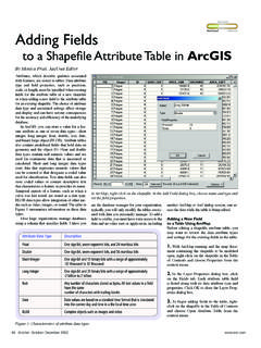
6 There isnothing preventing it from flowingdown the supporting columns to thedoors, finders, hood and trunk lid.(This can be easily confirmed by ex-amining the segment currents withinthe models reported by NEC.) Theresult being that the whole vehicle isradiating and is actually one half of adipole antenna system - the other halfbeing the roof-mounted vertical ele-ment. Granted, this is geometricallyand electrically a very lop-sided dipolebut, a dipole nonetheless. We knowthat changing the size and/or shapeof one arm (half) of a dipole will cer-tainly affect its pattern and gain. Thisis why we have the substantial differ-ences between the antenna patternsfor two cars although their roof dimen-sions are nearly , now that we have a better pic-ture of what s happening let s moveon and take a look at the rest of ourvehicle-dipole ResultsTo save you the drudgery of exam-ining a multitude of antenna plots re-quiring many pages of magazinespace let me give you a summary ofa couple items that were similar in amajority of all the (about 80% or more ofthe time there were exceptions) the1/4-wave whip had the highest highangle radiation component.
7 Elevationplots for the 1/4-wave revealed thatthe most of the energy being launchedbetween 7 and 80 . The 1/2-waveFigure 2 Elevation and azimuth patterns showing the comparison between the full and mid-sized cars for the threemost popular VHF Mobile antennasantenna s was slightly lower (7 - 70 )with the 5/8-wave the lowest (7 - 60 ).In all the elevation plots the lowestsignificant lobe was about 9 . In mostcases it was not the most significantlobe in amplitude, however, it is themost significant for long-range to-wards the horizon communicationshence I used a 9 elevation angle forcreating a series of azimuth antennapattern made two groups of azimuth first (Figure 3) displays the varia-tions resulting when the differentlength antenna elements are placedon the same vehicle. The second (Fig-ure 4) displays how the vehicles com-pare with one another using the samelength antenna element.
8 For best dis-play all plots are normalized however,the outer ring s dBi value is shown foreach found it a real eye opener to seethe amount of variations between themodels. A noteworthy exception wasthe 5/8-wavelength element that con-sistency produced the best omni-di-rection pattern. An additional ex-panded linear plot for the 5/8-wavevehicle combinations in Figure 5 andprovides a bit better the extent that the 5/8-wave pro-duces more gain, well, that s anothermatter. Note that in Figure 5 the pat-tern for the 5/8-wave/SUV combina-tion has an azimuth pattern that var-ies as much as 1 dB. Adding to thatyou can also note that dependingFigure 4 Azimuth patterns (9 elevation) displaying how the vehicles compareusing the same length antenna 3 Azimuth pattern variations (9 elevation) resulting with the differentlength antenna the vehicle selected and whatazimuth bearing is compared it is pos-sible for a 5/8-wave to have 2 dBgain over itself.
9 You might also con-sider that the maximum gain figuresshown for all the antenna and vehiclecombinations in Figures 3 & 4 variedless than 1 dB. So in the gain gameit s your s be realistic about gain. If youhave ever operated Mobile you knowit is not at all unusual to observe asignal rapidly fluctuating 20 dB ormore while driving. Under those con-ditions you aren t really going to dis-tinguish any gains under 3 dB one wayor the other. Possibly under marginalconditions with the vehicle at rest a 1or 2 dB improvement may make a dif-ference but it is highly doubtful, innormal Mobile operation, such a smallgain increase will be I stated at the onset I had origi-nally plan to investigate the gain of a5/8-wave monopole as used in UHFmobile operation. What I gleaned wasthat the 5/8-wave element was, in fact,operating as one arm of a dipole an-tenna system with the vehicle provid-ing the other half.
10 Subsequently thesize and shape of a vehicle has astrong influence, sometimes very pro-nounced, on the radiation pattern re-gardless what length antenna elementis used. Additionally, I found that it isnot possible to accurately predict howFigure 5 Expanded linear azimuthpattern (9 elevation) for the 5/8-waveantenna mounted on the four Mobile antenna system will performbased upon some other Mobile sys-tem unless the vehicles and antennainstallations are the same. To get anykind of meaningful estimation wouldrequire modeling each situation on acase by case in mind that the models I haveused are approximate and so are thefindings. To have better accuracy re-quires more exacting models. UsingCAD software to create wire-gridmodels that more closely conform tothe vehicles actual form and sizewould generate more valuable Win-Synth will import AutoCad (*.)