Transcription of Model 100 Series Kits - Baldwin Filters
1 Introductory Installation Information1. Always install DAHL 100 on the vacuum (suction) sideof transfer pump and ahead of any other filter : Ondomestic vehicles, remove the 3/8 inch hose from thetransfer pump and splice to the DAHL inlet hose. Onforeign engines, cut the 8 mm metric hose in halfbetween the factory filter and the steel line. Splice the twohalves to the DAHL inlet and outlet DAHL 100 as vertical as possible: Do not tiltmore than 10 . DAHL 100 as low as possible:The best locationfor filter operation is below the highest level, where thefuel not mount DAHL 100 directly on the engine:Vibration of the engine will loosen fittings and of DAHL 100:Priming eliminates air from the fuelsystem for smoother initial engine start up.
2 (See page 2.) not remove factory filter :Removal of new equipmentcomponents can void your warranty. Check with thevehicle dealer or leave the original filter in place. Alwaysinstall the DAHL 100 ahead of any fuel filter left in splicer installation:Hosesplicers normally do not requireclamps. If clamps are used, do notover tighten, as the hose could be cut by the fitting installation: Heating theend of the hose with hot water will easethe installation of all barbed Mounting Bracket for Model 100 StandardMountSideMountCrossbarMountUse the two top slots to mount the the top slot andthe center hole at the bottomto mount the the top openings with U-Bolts to mount the ModificationsBrackets can be modified to fit a specific engine compartmentlayout by:1.
3 Hacksawing a corner2. Drilling holes3. Bending in a viseDifferent brackets are in different kits . Another kit may have asuitable Installation Steps for Model 1001. Select mounting location: A DAHL 100 Series fuelfilter/water separator should be located between thetransfer pump and the steel line from the fuel tank. Itshould not interfere with normal engine maintenance,such as dipstick removal, access to coolant reservoir, sure the DAHL draincock is accessible. (Mountinglocation determines the hose routing.) Keep the hosesaway from abrasive points, fan belts or any moving illustration at right for mounting mounting bracket: Punch holes as required.
4 NOTE: Before drilling or punching, always check theopposite side for accessories, wires, lines or ducts. Model 100 Series KitsDiesel Fuel filter /Water Separators Installation InstructionsIllustrated is Model 140-10 for GM Cars. This typical mounting bracket can be placed in a variety of locations. Additional brackets for special and foreign models are also available. (See page 3.) pushlock fittings to open ends of DAHL inlet& outlet hoses: (See page 1, item 8.) attach both pushlock fittings to primer pump inline to inlet hose:Theprimer must be installedin the straight section ofthe hose to assure air-tight connection.
5 (Seepage 3.) DAHL filter as desired: Check and tighten allconnections, including bolts and nuts (except outletpushlock barbed fitting). Fuel System: Squeeze the primer bulb until thediesel fuel appears. Tighten the outlet pushlock barbedfitting. (Do not overtighten.) engine and purge remaining air:Check theinstallation. (See page 6.)Basic Installation Steps for Model 100, Cont brackets:If modification or substitution does notsolve the mounting problem, a customized bracket can easilybe made from heavy sheet metal or bent or welded Attach body clamp to mounting bracket:Refer to theappropriate diagram inset for assembly tighten draincock assembly to filter : Be sure thebowl plug is oiled and Screw elbow fittings into filter (Do Not Tighten):Grease or oil O-Ring.
6 Final position of the fittings isdetermined by the hose :To avoid cutting the O-Ring, do not over tighten Place filter into body clamp. Do not Bracketwithout BodyClampMounting Bracket with Body ClampImports7. Prepare inlet source:Locate the 8 mm(approximately 5/16")hose between thefactory filter and thesteel line from the fueltank. Cut in DAHL inlethose:Measure fromthe DAHL inlet port tothe half of the hoseattached to the steelline. Allow for slackand cut the inlet hose to size. Connect the hoses with balance ofDAHL hose to outletsource:Splice DAHL outlet hose to half ofmetric hose attached tothe factory filter with Prepare inlet source:Pull the standard 3/8"hose off the DAHL inlethose:Measure fromthe DAHL inlet port tothe existing hoseattached to the steelline.
7 Allow for slackand cut the inlet hose tosize. Use a splicer to connect the balance ofDAHL hose to outletsource:Attach theDAHL outlet hose tothe transfer pump. Usethe a 140-50 Hand PrimerThis hand primer is designed to make draining and/orelement changing Installation: Cut the hose a few inches from the inlet portat a straight section (as shown in the illustration). Installthe primer in-line. Tighten both clamps of air: Loosen the outlet pushlock barbedfitting to allow air to escape. Pump the primer bulb untilthe diesel fuel appears. Retighten the outlet Check for leaks:Check all connections.
8 If a leak developsaround the lid, the lid gasket may be improperly installed.#6 Hose (HH6)To TankHand Primer(140-50)Adjustable #6 Hose Clamps(2 Included)Push-onHose Fitting(1030-6x6)Inlet PortDAHL Primer Assembly DetailComplete Installation kits for Model 100-W/O(Order 100-W/O Separately)Most components listed in the kits are also available as individual part numbers. See complete DAHL price list for individual NoSizeQtyQtyQtyMounting Angle Bracket140-101 Body Clamp/Saddle Assembly111 Small Bolt - Clamp to Bracket1/4-20x5/8222 Small Nut1/4-20222 Small Flat Washer1/422 Small Lock Washer1/4222 Hose Clamp#6 (3/8)324 Primer Pump140-50 KIT#6111 Large Mounting Bolt5/16-24x3/42 Large Lock Washer5/162 Large Nut5/16-242 Fuel HoseHH6#6 (3/8)3 Flat Washer3/82 Elbow Fitting1010-6x6#6222 Pushlock Barbed Fitting1030-6x6#6222 Pushlock Barbed Hose Splicer#6 (3/8)
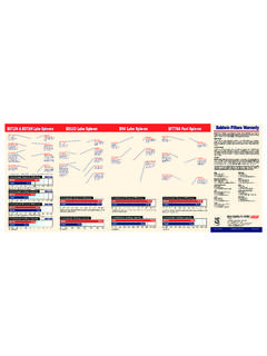
9 1 Inverted Female Fitting#61 Inverted Male Fitting#61140 KITfor Most GMC Cars143-6L KITfor Pre-1984 Light-Duty Trucks143-6L9 KITfor Ford & Light-Duty TrucksContents of Installation Kits3 Firewall Installationon General Motors Light-Duty TrucksUse DAHL Model 100-BMK or Model 100-W/O and 143-6L Installationon General Motors CarsUse DAHL Model 100-BMK or Model 100-W/O and 140 Installation DiagramsGeneral Motors Diesel CarsUse DAHL Model 100-BMK or Model 100-W/O and 140 100 Series Assembly Details5 DAHL Model 100 Parts ListCAUTIONDo NOT use any form of alcohol or any agent containing it inside or outside any DAHL BracketFitting(2 required - not included in unit)100-11 Bracket Bolt, Washer & Nut (2 sets required)100-14 Lid Cover100-13 Clamp Knob100-12 Seal Clamp with Knob100-15 Lid Cover Gasket100-17 Centerpipe O-Ring101*,-W,-30 Element w/Gasket100-36 Spring100-35 Centerpipe100-16 Body100-22 Reverse Flow Gasket100-23 Reverse Flow Washer100-24 Reverse Flow Ball100-19 Bowl Gasket100-25,26,27 Depressurizer Set100-21 Bowl100-20 Bowl Ring100-33 Socket Head Bolt10-32 x 3/4 (4 required)200-32O-Ring100-29 Bowl Plug100-30 Draincock (1/4 In.)
10 {Troubleshooting Air LeaksFittings:All fittingsmust be wrenchtight. Next, checkfor looseness, dents,misalignment orunmatched check fordamaged, dirty or ungreased O-Rings. (If a leak occursbetween the fuel tank and the inlet port, bubbles willappear at the depressurizer cone.)Draincock:If air bubbles arevisible immediately above thedraincock, check for defective,miscentered or an unlubricatedbowl plug gasket. Hand & Tube:Old fuel lines maycrack when moved. Check areas around the push-onfittings and hose clamps. Fix as needed.}