Transcription of Model 3196. S/N 788B861. Size 1 in. x1-1/2 in. x 8 in ...
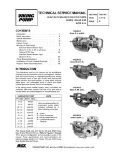
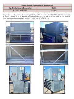
1 Goulds Centrifugal Pump Model 3196 Mfg: Goulds Model : 3196 Stock No. OIP016. Serial No. 788B861 Goulds Centrifugal Pump. Model 3196. S/N 788B861. Size 1 in. x1-1/2 in. x 8 in. Water flush double mechanical seals. Motor hp, 1,730 rpm, 230/460 V, 60 Hz, ,8 amps, 3 phase, Capacity 14 gpm. Overall Dimensions 35 in. L x 12 in. W x 15 in. H. Installation, Operation and Maintenance InstructionsANSI FAMILY2 ANSIFAM IOM - 7/04 Pump Safety TipsSafety Apparel: Insulated work gloves when handling hotbearings or using bearing heater Heavy work gloves when handling parts withsharp edges, especially impellers Safety glasses (with side shields) for eyeprotection, especially in machine shop areas Steel-toed shoes for foot protection whenhandling parts, heavy tools, etc. Other personal protective equipment to protectagainst hazardous/toxic fluidsCoupling Guards: Never operate a pump without a coupling guardproperly installedFlanged Connections: Never force piping to make a connection with apump Use only fasteners of the proper size andmaterial Ensure there are no missing fasteners Beware of corroded or loose fastenersOperation: Do not operate below minimum rated flow, orwith suction/discharge valves closed Do not open vent or drain valves, or removeplugs while system is pressurizedMaintenance Safety.
2 Always lock out power Ensure pump is isolated from system andpressure is relieved before disassembling pump,removing plugs, or disconnecting piping Use proper lifting and supporting equipment toprevent serious injury Observe proper decontamination procedures Know and follow company safety regulationsObserve all cautions and warnings highlighted inpumpInstallation, Operation and manual provides instructions for the Installation, Operation, and Maintenance of theGoulds Models 3196, CV 3196, HT 3196, LF 3196, NM 3196, 3198, and 3796. This manualcovers the standard product plus common options that are available. For special options,supplemental instructions are manual must be read and understood beforeinstallation and instruction manual covers several different pump models that all have a common powerend. Most assembly, disassembly, and inspection procedures are the same for all the , where there are differences, they are called out separately within the manual.
3 Thedesign, materials, and workmanship incorporated in the construction of Goulds pumps makesthem capable of giving long, trouble-free service. The life and satisfactory service of anymechanical unit, however, is enhanced and extended by correct application, proper installation,periodic inspection, condition monitoring and careful maintenance. This instruction manual wasprepared to assist operators in understanding the construction and the correct methods ofinstalling, operating, and maintaining these shall not be liable for physical injury, damage, or delays caused by a failure toobserve the instructions for installation, operation, and maintenance contained in intalled in potentially explosive atmospheres, the instructions that follow the Ex symbolmust be followed. Personal injury and/or equipment damage may occur if these instructions arenot followed. If there is any question regarding these requirements or if the equipment is to bemodified, please contact a Goulds representative before is valid only when genuine Goulds parts are of the equipment on a service other than stated in the order will nullify the warranty.
4 Unless written approval is obtained in advance from Goulds by an authorized Goulds representative is recommended to assure proper manuals can be obtained by contacting your local Goulds representative or bycalling MANUAL EXPLAINSnProper InstallationnStart-up ProceduresnOperation ProceduresnRoutine MaintenancenPump OverhaulnTrouble ShootingnOrdering spare or Repair PartsANSIFAM IOM - 7/0434 ANSIFAM IOM - 7/04 TABLE OF CONTENTSPAGESECTION7 SAFETY11 GENERAL INFORMATION19 INSTALLATION35 OPERATION45 PREVENTIVE MAINTENANCE53 DISASSEMBLY & REASSEMBLY109 spare AND REPAIR PARTS117 APPENDIX117 IFrame Lubrication Conversion121 IIInstallation Instructions for Goulds ANSI Coupling Guards125 IIISet Up and Alignment129 IVLabyrinth Seal Installation Instructions131VC-Face Adapter Installation Instructions133VI3198 Teflon Sleeve Field Replacement Procedure135 VII-1 Double Row Angular Contact Bearing Installation Instructions137 VII-2 Duplex Angular Contact Bearing Installation Instructions139 VIIII npro Labyrinth Oil Seal Installation InstructionsANSIFAM IOM - 7/045123456786 ANSIFAM IOM - 7 7 GENERAL 7 DEFINITIONST hese pumps have been designed for safe andreliable operation when properly used and maintainedin accordance with instructions contained in thismanual.
5 A pump is a pressure containing device withrotating parts that can be hazardous. Operators andmaintenance personnel must realize this and followsafety measures. Goulds Pumps shall not be liablefor physical injury, damage or delays caused by afailure to observe the instructions in this this manual the wordsWARNING,CAUTION,ELECTRICAL, ATEX, andNOTE areused to indicate procedures or situations whichrequire special operator attention:s!WARNINGO perating procedure, practice, etc. which, if notcorrectly followed, could result in personalinjury or loss of !CAUTIONO perating procedure, practice, etc. which, if notfollowed, could result in damage or destructionof equipment is to be installed in apotentially explosive atmosphere and theseprocedures are not followed, personalinjury or equipment damagefrom an explosion may care must be taken whenelectrical power source to the equipment : Operating procedure, condition, is essential to !
6 WARNINGPump shall never be operated without couplingguard installed !CAUTIONT hrottling flow from the suction side may causecavitation and pump impeller adjustment could causecontact between the rotating andstationary parts, resulting in a spark andheat out driver power to prevent electricshock, accidental start-up and : Proper alignment is essential for longpump IOM - 7/0471 GENERAL PRECAUTIONSs!WARNINGP ersonal injuries will result if proceduresoutlined in this manual are not !NEVER apply heat to remove impeller. It mayexplode due to trapped !NEVER use heat to disassemble pump due torisk of explosion from trapped !NEVER operate pump without coupling guardcorrectly !NEVER operate pump beyond the ratedconditions to which the pump was !NEVER start pump without proper prime (allmodels), or proper liquid level in self-primingpumps ( Model 3796).l!NEVER run pump below recommendedminimum flow or when !
7 ALWAYS lock out power to the driver beforeperforming pump !NEVER operate pump without safetydevices !NEVER operate pump with discharge !NEVER operate pump with suction NOT change conditions of servicewithout approval of an authorized PREVENTIONIn order to reduce the possibility of accidental explosions in atmospheres containing explosivegasses and/or dust, the instructions under the ATEX symbol must be closely followed. ATEX certification is a specification enforced in Europe for non- electrical and electrical equipmentinstalled in Europe. The usefulness of the ATEX requirements are not limited to Europe, andare useful guidelines for equipment installed in any potentially explosive ATEX CONSIDERATIONSAll installation and operation instructions in this manualmust be strictly adhered to. In addition, care must betaken to ensure that the equipment is properlymaintained. This includes but is not limited to:1.
8 Monitoring the pump frame and liquid Maintaining proper bearing Ensuring that the pump is operated in theintended hydraulic IOM - 7/04 ATEX IDENTIFICATIONFor a pumping unit (pump, seal, coupling, motor andpump accessories) to be certified for use in an ATEX classified environment, the proper ATEX identificationmust be ATEX tag would be secured to the pump or thebaseplate on which it is mounted. A typical tag wouldlook like this:The CE and the Ex designate the ATEX code directly below these symbols reads asfollows:II= Group 22= Category 2G/D= Gas and Dust presentT4=Temperature class, can be T1 to T6(see Table 1)Table 1 CodeMax permissiblesurface temperatureoF(oC)Max permissibleliquid temperatureoF(oC)T1842 (450)700 (372)T2572 (300)530 (277)T3392 (200)350 (177)T4275 (135)235 (113)T5212 (100)Option not availableT6185 (85)Option not availableThe code classification marked on the equipmentshould be in accordance with the specified areawhere the equipment will be installed.
9 If it is not,please contact your ITT/Goulds representative USEThe ATEX conformance is only applicable when thepump unit is operated within its intended use. Allinstructions within this manual must be followed at alltimes. Operating, installing or maintaining the pumpunit in any way that is not covered in this manual cancause serious personal injury or damage to theequipment. This includes any modification to theequipment or use of parts not provided by there is any question regarding the intended use ofthe equipment, please contact an ITT/Gouldsrepresentative before MONITORINGFor additional safety precautions, andwhere noted in this manual, conditionmonitoring devices should be used. Thisincludes, but is not limited to: Pressure gauges Flow meters Level indicators Motor load readings Temperature detectors Bearing monitors Leak detectors PumpSmart control systemFor assistance in selecting the proper instrumentationand its use, please contact your IOM - 7/049110 ANSIFAM IOM - 7/04 GENERAL INFORMATIONPUMP 11 PARTS 13 NAMEPLATE 16 RECEIVING THE 17 Storage 17 PUMP DESCRIPTIONANSIFAM IOM - 7/04112 ModelPump DescriptionSize GroupsNo.
10 OfSizes3196 The Model is based on 5 power ends and 29 hydraulic pump 3196 is a horizontal overhung, open impeller, centrifugal pump that meets therequirements of ANSI 3196 The Model is based on four power ends and seven hydraulic pump CV 3196 is a horizontal overhung, recessed impeller, centrifugal pump. It isspecifically designed to handle bulky or fiberous solids, air or gas entrained liquids, orshear sensitive 3196 The Model HT 3196 is based on 4 power ends and 28 hydraulic pump HT 3196 is a horizontal, centerline mounted, overhung, open impeller, centrifugalpump that meets the requirements of ANSI 3196 The Model is based on 3 power ends and 4 hydraulic pump LF 3196 is a horizontal overhung, open impeller, centrifugal pump that meets therequirements of ANSI It is designed specifically for low flow high 3196 The Model is based on 2 power ends and 13 hydraulic pump NM 3196 is a horizontal overhung, open impeller, centrifugal pump that meets therequirements of ANSI It is made of a fiber reinforced vinylester to handle Model is based on 2 power ends and 4 hydraulic pump 3198 is a horizontal overhung, open impeller.