Transcription of Model 7125 Manual Sample Injector - Schambeck …
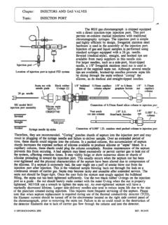
1 Operating Instructions Model 7125 Manual Sample DESCRIPTIONM odel 7125 is a six-port Sample injectionvalve in which the Sample is loaded througha built-in needle port in the front of the 1 shows the flow diagram of thevalve. The circles represent the ports in thevalve stator. The dark and white groovesrepresent the connecting passages in therotor seal. The large circle represents theneedle Sample loop is loaded through theneedle port in the LOAD position. Rotationof the knob 60 switches the valve fromLOAD to INJECT. In INJECT the mobilephase flows through the loop. SUPPLIED WITH THE VALVES upplied with the valve in a separate bagare RheFlex fitting sets for all ports and theitems shown below. A 20 L Sample loop isstandard with the valve. Hex Keys Needle Port Cleaner Mounting Screws Vent TubesThe #22 gauge needle supplied in the valveshould be removed from the needle portbefore using the SPECIFICATIONS Maximum Temperature: 80 C Maximum Operating Pressure: 48 MPa(482 bar, 7000 psi) Flow Passage Diameters: mm ( ")and mm ( ") Wetted Surfaces: stainless steel, ceramic,and an inert IMPORTANT SAFETY Warning:When using Sample loopslarger than 100 L, shield yourself frommobile phase coming out of the needle portwhen the valve is turned from INJECT toLOAD.
2 Example: 1 mL loop ejects 20 Lupon decompression from 19 MPa (200 bar,2898 psi). Warning:When using the Needle PortCleaner, empty the syringe slowly to preventsolvent from squirting back at Caution:Rinse the valve with waterafter using buffer solutions to preventcrystals from forming, which can causescratches on the rotor USING PROPER SYRINGESUse syringes with #22 gauge syringeneedle,without electro taper and with 90 point style(square cut). Using the incorrect needle sizewill damage the INSTALLATION a) To mount the valve on a panel, removethe handle by loosening the two handle setscrews. Use the two screws supplied tofasten the valve to a ) Replace the handle by tightening the twoset screws on the two flats of the ) Connect the two vent tubes (supplied) toPorts 5 and 6. Place the outlet ends of both atthe same horizontal level as that of theneedle port to avoid siphoning.
3 See Figure ) Connect the pump to Port 2 and thecolumn line to Port 3. Leave the columndisconnected from the valve during FLUSHING THE INJECTORIn INJECT, flush the needle port with 1 mLof mobile phase, using the Needle PortCleaner as shown in Figure 3. At this time,the pump flushes the loop. See Warning MAKING AN INJECTIONT here are two common methods of loadingthe Sample loop complete or partial filling. COMPLETE LOOP FILLINGIn complete-filling, the volume of sampleinjected is set by the volume of the loop (thisincludes the valve passages). This methodproduces the highest the loop with at least two to fiveloop volumes of Sample . Six to ten loopvolumes will provide even better excess of Sample is needed becausemobile phase near the wall of the loop isdisplaced slowly due to the laminar floweffect shown in Figure completely fill the loop:a) See Warning turn to ) Insert the syringe into the needle will feel tightness during the last 2-3mm of travel as the needle passes through theneedle seal and then stops against the ) Load the ) Leave the syringe in and turn to PARTIAL LOOP FILLINGIf you only have small quantities of Sample ,this is the method of choice.
4 In the partial-filling method the volume of Sample injectedis set by the syringe. In this method, no morethan half a loop volume of Sample should beloaded into the loop. For example, load nomore than 10 L into a 20 L loop. Withlarger volumes some of the Sample is lost outVent Line 6. This is because Sample flowsdown the center of the loop at twice theaverage velocity due to the laminar floweffect shown in Figure A (LOAD)134562 ColumnNeedle PortSample LoopPumpWastePosition B (INJECT)134562 Needle PortWastePumpColumnSample LoopFig. 1. Model 7125 flow 2. Correct position of vent BarrelNeedle Port CleanerHandle AssemblyNeedle GuideFig. 3. Use of Needle Port 1 of 22320157D6/01 Fig. 4. Laminar flow WallMobile PhaseRheodyne LLC A Unit of IDEX Corporation 600 Park Court, Rohnert Park, CA 94928 (707) 588-2000 Fax (707) partially load the loop:a) In INJECT, use the Needle Port Cleanerto flush out the needle port with about 1 mLof mobile phase.
5 This will flush outcontamination from the earlier liquid will exit out Vent Line ) Follow steps a-din Section ADJUSTING FOR LEAKAGE ORHIGHER PRESSURE OPERATIONThe three small set screws in the stator (seeFigure 5) have been factory set so that whenthe three stator screws are fully tightened, thespring force between the valve rotor andstator is sufficient to hold the indicatedpressure. If leakage is to be corrected, or ifoperation at a higher pressure is to be done,proceed as follows: The three set screwsshould be loosened about 1/20 turn each (18 of rotation) and the three stator screwstightened an equal amount. If this newsetting fails to accomplish leak-freeoperation at the desired pressure, repeat theprocedure by an additional 1/20 turn. Avoidexcessive tightening which will onlyincrease wear of the rotor seal.
6 If it isnecessary to loosen spring tension, either tolower the operating pressure, or to adjust fora new rotor seal, which may be thicker thanthe one being replaced, reverse the aboveprocedures. For example, first loosen thestator screws, then tighten the set leakage cannot be stopped by tighteningthe valve, or if, as a result of tightening tostop the leakage, the handle is too hard toturn, the rotor seal needs replacing. See MAINTENANCEThe only parts that may need eventualreplacement are the rotor seal and stator faceassembly. The main causes of early failure are:a) The wrong needle tip can damage theceramic stator face which then causes deepscratching of the rotor seal ) Abrasive particles in the Sample canscratch the rotor seal DISASSEMBLYTo disassemble the valve, refer to Figure 5and proceed as follows:a) Remove the three stator ) Remove the stator, stator face assembly,and stator ring from ) Pull the rotor seal off the ) Remove the isolation REASSEMBLYTo reassemble the valve, refer to Figures 5and 6 and proceed as follows:a) Slip the new isolation seal (open sidefacing the handle) onto the stator end of theshaft assembly next to the bearing ) Line up the rotor seal as shown in Figure6.
7 The rotor seal slots face the ) Replace the stator ring so that the 60 stop pins enter the mating holes in the ) Put the stator face assembly on the assembly is symmetrical and can bemounted either of two ) Replace the stator face assembly andstator on the valve so that the pin in the statorring enters the mating hole in the ) Replace the three stator screws andtighten each screw a little at a time to keepthe stator surface parallel to the stator ringsurface. If the three set screws in the statorwere left unchanged, tighten the three statorscrews a 1/2 turn past fingertight. The threeset screws will ensure that the gap betweenstator and stator ring is uniform and in theoriginal position before ) If the set screws need adjusting becausea new rotor seal was installed or becauseleakage has to be stopped, each set screwshould be turned an equal amount to ensurethat after the stator screws are retightened thegap between the stator and stator ring isuniform all around.
8 Refer also to Section OPERATING SUGGESTIONS LEAKAGEIf you see liquid between the stator andstator ring, or from the needle port or a venttube, tighten the pressure adjusting screw asexplained in Section If this fails to stopthe leak then replace the rotor seal and/orstator face NEEDLE SEAL LEAKAGES ince the outside diameter of syringeneedles can vary, the needle seal (Teflon1sleeve in the rotor seal) may not seal firmlyaround a needle that is smaller than will result in the loss of accuracy inloading the Sample . To make a good seal,remove the needle from the needle port andpush in on the plastic needle guide with theeraser end of a pencil. Repeat if USE OF AQUEOUS BUFFERS ORSALT SOLUTIONSTo prevent the formation of salt crystals inthe valve which can scratch the rotor seal,flush out the flow passages and the needleport with water after using salt USE OF HIGH pH SOLUTIONSThe standard rotor seal in Model 7125 isVespel1, a polyimide with good wearresistance.
9 Vespel is sensitive to alkalineattack when exposed to solutions having apH of 10 or more. Use a PEEK or Tefzel1rotor seal, which tolerates pH 0 to 14, foralkaline ACCURACY OF Sample LOOPSS ample loop sizes are not actual values. Theactual volume can differ by 10% for a 20 L loop. There is a greater difference forsmaller loops. Use partial-filling if you mustknow the actual volume RECOMMENDED SPARE PARTSR heodyne offers a RheBuild Kit forModel 7125 that includes all parts, tools, andinstructions to maintain the qualityperformance of your valve without separatepart RheBuild Kit for WARRANTYAll Rheodyne products are warrantedagainst defects in materials andworkmanship for a period of one yearfollowing the date of shipment by will repair or replace anyRheodyne product that fails during thewarranty period due to a defect in materialsor workmanship at no charge to thecustomer.
10 The product must be returned toRheodyne s factory in original packaging orequivalent, transportation prepaid. Damageoccurring in transit is not covered by thewarranty. This limited warranty isRheodyne s sole warranty of its products,and all other warranties of merchantability orfitness for any particular purpose are herebydisclaimed. Under no circumstances willRheodyne be liable for any consequential orincidental damages attributable to a claimedfailure of a Rheodyne product, even ifRheodyne has been placed on notice ofpossibility of such 2 of 22320157D6/01 Fig. 6. Correct position of rotor seal (slots facethe stator).Fig. 5. Exploded view of Model Assembly Handle Set Screws (2) Needle Guide Shaft Assembly Body Thrust Bearing Spring Washers (4) Needle Port TubeAssemblyBearing Ring Isolation Seal Rotor Seal Stop Pins (2) Stator Ring Stator Face Assembly Stator Set Screws (3) Stator Stator Screws (3) 1 Teflon, Vespel, and Tefzel are trademarks of DuPontRheodyne LLC A Unit of IDEX Corporation 600 Park Court, Rohnert Park, CA 94928 (707) 588-2000 Fax (707)