Transcription of Model BO 2 BUMP OUT 2 - Ready Access -Home
1 Pass- Thru Windows Model BO 2 BUMP OUT 2 Model BO 4 BUMP OUT 4 2 TABLE OF CONTENT Topic Page 3 3 4 Disclaimer Contact Sheet Introduction Product Information Description 4 Safety Information 5 Warranty/Specifications 6 Dimensions 7 Installation Procedures Tools needed 8 Materials Needed 8 Physical Installation 9 Semi Automatic Installatioin 13 Electrical Installation 14 Initial Operations and Testing 16 Adjustments and Calibrations 17 Operational Procedures Modes of Operation 19 Operations 19 Maintenance Maintenance Schedule 20 Daily 20 Monthly 20 Yearly 20 Service Troubleshooting Guide (Cause and Effect) 21 Parts Lists Parts List Common To Both Models 24 Parts List Model Specific 25 Drawings - Exploded Views / Schematics 27 3 DISCLAIMER Ready Access DISCLAIMS ANY LIABILITY FOR ANY DAMAGE OR HARM CAUSED TO THE BO-2 AND BO-4 DRIVE-THRU WINDOWS, IT S OPERATOR OR ANY OTHER EQUIPMENT HOWEVER CAUSED IF THE BO-2 DRIVE-THRU WINDOW IS INSTALLED, REPAIRED OR SERVICED BY ANYONE OTHER THAN AN AUTHORIZED SERVICE ENGINEER OR CONTRARY TO THE MANUFACTURERS WRITTEN INSTRUCTION CONTAINED HEREIN.
2 THIS MANUAL IS INTENDED FOR USE BY THE IN-HOUSE OR AUTHORIZED FIELD SERVICE ENGINEERS AND SALES REPRESENTATIVES The manufacturer maintains the right to update, add or issue a new service manual at any time without notice, thereby rendering all previous issues obsolete. Please write the Serial Number and Installation Date for your drive-thru window in the spaces provided. Serial Number Date of Installation Contact Information For sales and service contact Ready Access Tel: 630-876-7766 1815 Arthur Drive Tel: 800-621-5045 West Chicago, Illinois 60185 Fax: 630-876-7767 Email: Website: 4 INTRODUCTION The Ready Access window is quality designed to give you years of reliable, trouble-free service. Each window is shipped pre-assembled, fully glazed and Ready for installation. All Ready Access windows are thoroughly tested prior to shipping. The original Ready Access Bump-Out window design is recognized throughout the world as the industry standard with more units installed than any other window of its type.
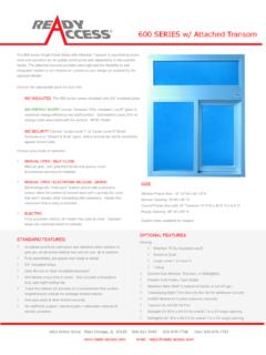
3 By design, this ruggedly constructed unit combines functional superiority and practicality - all in an attractive window that can match virtually any building exterior. The BO-2 and BO-4 come in two versions, semi-automatic and electric. The electric version is fully automatic with a manual override in case of a power outage. The doors will open and close by stepping into an out of the light beam sensor. Electric and Semi-Automatic models meet health department requirements for self-closing units. PRODUCT INFORMATION 19"W x 18"H Service Opening (BO-2)This large service opening is perfect for virtually any size order, from pizza to ribs to beverage cartons. 19"W x 32"H Service Opening (BO-4)This large service opening makes the Bump-Out 4 ideal for the bulkiest of orders. Frame SizeStandard window dimensions are 27 3/4"W x 48 3/4"H. Panoramic ViewThe classic Ready Access Bump-out design promotes visibility and personal contact byoffering a three sided, 180-degree view of cars and customers.
4 Quality ConstructionAnodized aluminum extrusions, stainless steel and 1/4" tempered glass combine to giveyou an attractive window that not only enhances building exteriors, but will not rust, pit orweather. Track free bottom sill provides for a contaminant free surface. Fully Assembled, Ready to InstallReady Access windows are shipped completely pre-assembled, and fully glazed forlower installation costs. Normal installation takes less than two hours. Five Day ShippingReady Access will ship any standard window order in 5 days from receipt of order. Warranty and Service SupportBump-Out 2 and Bump-Out 4 come with a one year limited warranty on parts and labor. In addition, each unit is backed by a worldwide service organization. 5 SEMI-AUTOMATIC OR FULLY-AUTOMATIC SERVICE OPENINGS Semi- Automatic BO-2 and BO-4In a Semi-Automatic operation, simply release the top lock and push on the push pad to open the door.
5 Both doors part from the center and easily open. A retrofit kit is available to convert semi- automatic models into fully automatic units. Fully Automatic BO-2 and BO-4 onlyThe operator simply steps into an electronic light beam that opens the door panelsautomatically. The door panels automatically close when the operator steps away fromthe electronic light OPTIONS Bump-Out 2 and Bump-Out 4 are available in statuary bronze or clear anodized aluminum. Tinted glass is available upon request. Powder coat painting is available in a wide range of custom Information WARNING: To avoid the risk of fire, electric shock or injury to persons, observe the following: 1. Before servicing or cleaning the unit, switch the power off at the mechanical switch near the unit(Installed by an Electrician) or the electrical entry service panel/circuit breaker. (Load Center) OSHA LOCK OUT TAG OUT procedures are to be observed to prevent power from beingswitched on Any Installation and / or Electrical work must be done by QUALIFIED persons in accordance withall applicable codes / standards and manufacturers recommendations and NOT insert fingers and / or foreign objects into the Drive-Thru NOT block or tamper with the unit in any manner while it is in This product must not be used in Potentially Dangerous locations such as Flammable, ExplosiveChemical laden WARRANTY: Ready Access will only accept responsibility for manufacturing defects in the product s construction and/or materials.
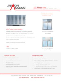
6 Adjustments required during installation are the responsibility of the installer or contractor and will not be covered under warranty. Problems caused by improper installation are the responsibility of the installer or contractor and will not be covered under warranty. SPECIFICATIONS AND PERFORMANCE Fully-Automatic Unit Voltage Model Number USA International Actual Unit Amps Dimensions In Inches W x H x D Weight In Shipping Carton BO-2 - E 110/120 VAC 60Hz 220/240 VAC 60Hz 15 A (US) 8 A (Int l) 27 x 48 x 15 156 lbs BO-4 - E 110/120 VAC 60Hz 220/240 VAC 60Hz 15 A (US) 8 A (Int l) 27 x 48 x 15 156 lbs Dimensions 7 BO-4 SERVICE OPENING19" W x 32" HBO-2 SERVICE OPENING19" W x 18" H1534"[ ]4834"[ ]483 4"[ ]153 4"[ ]2734" [ ]2734" [ ]Figure 1 8 Installation Procedures Tools required to perform the installation Electric Drill Metal Drill bits (3mm) (6mm) (13mm)1 (25mm) Screwdrivers Slotted and Phillips Hacksaw Jack / Utility Knife Flat File Coarse Caulking gun Nut Driver Extension Cord Masonry drill bit (6mm)1 (25mm)1 (38mm) Masonry Hole Saw 1 (25mm)
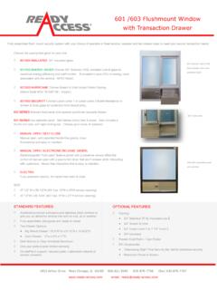
7 Channel Lock Pliers Tape Measurer Wire Cutter Step Ladder LevelMaterials required for installation Window framing, architect specified and installed in building.( Ready Access recommended material is (3mm) x 1 ( ) x 4 (102mm) hollowaluminum tubing or glazing channel) Electrical Tape Wire Nuts Caulking silicone (Color specific to the color of window) Connectors for conduit as required Shingle type shims as required to level and plum the window9 Physical Installation Before you begin installing your Ready Access Drive-Thru Window, you must determine what type of installation will be required. Wood Frame, Masonry Framing, etc. Please refer to the details below to pick which one bests fits your application. WARNING: TWO PEOPLE ARE REQUIRED FOR THE LIFTING AND INSTALLATION OF THE WINDOW. NOTE: There are two wall-mounting applications. The mounting space can be surrounded either by sidelights (windows) or masonry.
8 The illustrations below will show both configurations. (Figure 2) Figure 2 PICTURED BO-4 28 1/4" 49 1/4" 28"49" 10 1. Confirm that the customer-supplied frame is made to accommodate the dimensions as illustrated on page 6. 2. Confirm that AC power has been run and is Ready for connection to the window. 3. Check shipping carton for any shipping damage and remove window from the carton. 4. Check window for any shipping damage. 5. Once the application has been determined, check the daylight opening of the frame being used. The opening dimensions should be 24 wide x 34 high. 6. For a Fully-Automatic installation, check for the electrical hook-up. The AC electric should be installed directly from the breaker box (Load Center) to the window opening before the installation of the window. 7. Using the paper mounting template, drill a quantity of 10, diameter pilot holes for mounting.
9 (See Figure 3) OUTSIDE ONLY DO NOT DRILL THROUGH THE FRAME. Figure 3 8. Remove the template and drill 10, hole using the pilot holes. OUTSIDE ONLY DO NOT DRILL THROUGHT THE FRAME. 11 9. For Semi-Automatic installations, Drill a 1 hole through the wall as illustrated in Figure 4. (The dimensions shown are from the inside of the building.) (308mm) Figure 4 10. For Fully-Automatic, Drill a 1 hole through the wall as illustrated in Figure 4. (The dimensions shown are from the inside of the building.) ( ) ( )ROUGH OPENING IS SHOWN FROMTHE INSIDE LOOKING OUTDIMENSIONS ARE TAKEN FROM THEINSIDE DAYLIGHT OPENING OF THE FRAME Figure 5 12 11. Requiring 2 people, remove Ready Access Window from carton and place on top of carton lid to prevent scratching. 12. Person number 1 should remove the bottom cover from the window and organize the mounting hardware.
10 Person number 2 should apply a bead of caulk to the outside surface of the building window frame. (Reference 1/2" drilled holes for mounting window.) 13. Requiring 2 people, stand window upright. With one person on each side of the window, lift the window into position, aligning the counter top with the building frame sill. With one person holding the front of the window from falling forward, the other person from the inside will start inserting 5 of the well nuts with the washers and bolts through the inside top of the window into the building frame. (Figure 6) (If mounting through wood, use lag bolts. If mounting to masonry, use mason anchors) Figure 6 From the outside, insert the remaining 4 well nuts and fasten with the bolts and washers provided, through the bottom, underneath the counter, into the building frame. Figure 7 13 14. DO NOT TIGHTEN - Shim unit to be square and plum.