Transcription of Model KCT Automatic Transfer Switches MPAC …
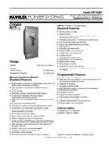
1 Model KCT. Automatic Transfer Switches MPAC 1000t Controller Standard Features D Microprocessor controller D Real-time clock with battery backup D Broadrange voltage sensing (208--600 VAC) with 2%. accuracy on both sources D Frequency sensing with 1% accuracy on both sources D Environmentally sealed user interface D Keypad with tactile feedback pushbuttons D LED indicators D Selectable operating modes D Programmable inputs and outputs D Load/no load exercise function D Anti-single phasing protection D Load control inputs and outputs D Phase rotation sensing D Time-stamped event log D Gold-flashed engine start contacts D Modbusr communication with network and setup Ratings connections Voltage: 208--600 VAC 50/60 Hz MPAC 1000t Controller Current: 30--4000 amps Programmable Features Standard Contactor Features D System voltage and frequency D Open-transition operation with either Automatic or D Adjustable over/undervoltage and over/underfrequency for non- Automatic control the normal and emergency sources D 2, 3, or 4 poles D Adjustable time delays D Electrically operated, mechanically held D Commit/no commit Transfer D Double-throw, inherently interlocked design D ABC/BAC phase rotation selection with error detection (break-before-make power contacts) D Resettable historical data D Solid, switched, or overlapping neutral (make-before-break D In-phase monitor type) D Password protection D High withstand and closing ratings D Design suitable for emergency and standby applications on Accessories all classes of load, 100% tungsten rated through 400 amps D Programmable input/output (I/O)
2 Modules with two inputs D Open-transition Transfer time less than 100 milliseconds and six outputs (isolated SPDT form C contacts, output (6 cycles @ 60 Hz) rating 2 amps @ 30 VDC/250 VAC); four I/O module maximum D Silver alloy main contacts D Three-stage charging, dual-output battery charger D Front-accessible contacts for easy inspection (6 amps @ 12 VDC/3 amps @ 24 VDC). D Front-replaceable main and arcing contacts (600--4000 amps). D Padlockable user interface cover D Reliable, field-proven solenoid mechanism D Preferred source switch D Switching mechanisms lubricated for life D Supervised Transfer control switch D Internal manual operating handle D Setup software D Main shaft auxiliary contacts D Line-to-neutral monitoring D Chicago alarm module D External battery supply module (allows extended engine start Modbusr is a registered trademark of Schneider Electric. time delay). G11-80 ( Model KCT Transfer Switch) 1/07o Page 1.
3 Controller Features Standard Controller Features Communications User Interface Keypad D Serial port for PC connection D Start/end system test D Modbusr network interface D Set/end exercise Programmable Features D End time delay Use a personal computer with the optional setup software or a D Lamp test/service reset Modbusr link to view, select, or adjust programmable features. User Interface Indicators Programmable Features*. D Contactor position: Normal, Emergency D System voltage[. D Source available: Normal, Emergency D System frequency[. D Service required: immediate, maintenance D Single/three-phase operation[. D Not in Automatic mode D ABC or CBA phase rotation (ABC). D Four-stage time delay remaining D In-phase monitor (disabled). D Exercise: load, no load, set/disabled D Commit/no commit switch (no commit). D Test: load, no load D User-defined password D Load control active: peak shave, pre/post- Transfer signal D Calendar mode exerciser (up to 21 events).]]]
4 D In-phase monitor active Programmable Inputs and Outputs Selectable Operating Modes*. Use a personal computer with the optional setup software or a D 1 week/2 week manually set exercise (1 week) Modbusr link to define inputs and outputs. D Disable/enable exercise (enable). Programmable Inputs D Load/no load exercise (no load). D End time delay input (default). D Load/no load test (load). D Inhibit Transfer D Enable/disable Transfer (enable). D Low battery fault Programmable Inputs (factory settings) D Load shed (forced Transfer to OFF; programmed-transition D End time delay models only). D Peak shave/area protection D Peak shave/area protection input (default). D Remote common fault Outputs D Remote test D Generator engine start, normally closed gold-flashed contact rated 2 amps @ 30 VDC/250 VAC Programmable Outputs D Pre- Transfer load control, one normally open contact D Auxiliary switch fault rated 10 amps @ 30 VDC/250 VAC.
5 D Common fault D One programmable output, factory-set to load bank control D Contactor position isolated SPDT form C contact rated 2 amps @ 30 VDC/250 VAC D Exercise active D Failure to acquire standby source Software Event Monitoring D Failure to Transfer fault Use a personal computer with the optional setup software or a Modbusr link to view historical data and system events. D Generator engine start D Historical data (total and resettable) D Load bank control (default). D System events (time and date-stamped) D Load control (pre/post- Transfer , up to 9 outputs). D System faults (time and date-stamped) D Loss of phase fault D Line-to-line voltage D Low backup battery D System frequency D Modbusr-controlled relay outputs (4 maximum). D Time delay active D Not in Automatic mode D Time delay remaining D Non-emergency Transfer D System status D Over and undervoltage faults D Source available D Over and underfrequency faults D Contactor position D Peak shave/area protection active D Exerciser schedule, mode, and time remaining on active D Phase rotation error exercise D Source available D Test active * Factory default settings are shown in parentheses.
6 All settings are stored in non-volatile memory. [ System parameters set per order. G11-80 ( Model KCT Transfer Switch) 1/07o Page 2. Controller Features, continued Application Data Voltage and Frequency Sensing UL-Listed Solderless Screw-Type Terminals for External Power Connections Parameter Default Adjustment Range Normal, Emergency, and Load Terminals Undervoltage pickup 90% of nominal 85%--100% of nominal Maximum Undervoltage dropout 90% of pickup 75%--98% of pickup Switch Rating Number of Range of Wire Sizes, (Amps) Cables per Pole Copper or Aluminum ]. Overvoltage dropout 115% of nominal 105%--135% of nominal*. 30--230 1 #14 AWG to 4/0 AWG ]. Overvoltage pickup 95% of dropout 95%--100% of dropout 1 #4 AWG to 600 MCM. Voltage dropout time sec. sec. 260 400. 260--400. Underfrequency pickup 90% of nominal 85%--95% of nominal 2 #1/0 AWG to 250 MCM. Underfrequency 600 2 #2 AWG to 600 MCM. 99% of pickup 95%--99% of pickup dropout 800--1200 4 #1/0 AWG to 750 MCM.
7 Overfrequency dropout 101% of pickup 101%--105% of pickup 1600--2000 6 #1/0 AWG to 750 MCM. Overfrequency pickup 110% of nominal 105%--120% of nominal 2600--3000 12 #1/0 AWG to 750 MCM. Frequency dropout time 3 sec. sec. 4000 Bus Bar * 690 volts, maximum ] 230 amp/600 volt use copper only Adjustable Time Delays Input andOutput Connection Specifications Adjustment Time Delay Default Range Component Number of Wires Wire Size Range Engine start 3 sec. 0--6 sec.[ Terminal strip I/O terminals 1 #12--24 AWG. Preferred to standby 1 sec. I/O module terminals 1 #14--24 AWG. Standby to preferred 15 min. Engine cooldown 0 min. Auxiliary Position Indicating Contacts (rated 10 amps @ 32 VDC/250 VAC). Failure to acquire standby source 1 min. 0 60 min 0--60 [. min.[ Number of Contacts Indicating Pre- Transfer to preferred signal 3 sec. Normal, Emergency Pre- Transfer to standby signal 3 sec. Switch Rati ng Open- Programmed- (Amps) Transition Transition Post- Transfer to preferred signal 0 sec.]]
8 30--104 2, 2 . Post- Transfer to standby signal 0 sec. 150--400 2, 2 2, 2. [ Adjustable in 1 second increments. Can be extended to 60 minutes with an External Battery Supply Module Kit. 600--800 2, 2 6, 6. 1000--3000 8, 8 7, 7. 4000 4, 4 4, 3. Environmental Specifications Operating Temperature --20 C to 70 C (--4 F to 158 F). Storage Temperature --40 C to 70 C (--40 F to 158 F). Humidity 5% to 95% noncondensing Altitude 0 to 3050 m (10000 ft.) without derating G11-80 ( Model KCT Transfer Switch) 1/07o Page 3. Codes and Standards The ATS meets or exceeds the requirements of the following D NEMA Standard IC10--1993 (formerly ICS2--447), specifications: AC Automatic Transfer Switches D Underwriters Laboratories UL 508, Standard for Industrial D EN61000-4-5 Surge Immunity Class 4. Control Equipment (voltage sensing and programmable inputs only). D Underwriters Laboratories UL 1008, Standard for Automatic D EN61000-4-4 Fast Transient Immunity Severity Level 4.]
9 Transfer Switches for Use in Emergency Standby Systems D IEC Specifications for EMI/EMC Immunity: D Underwriters Laboratories Inc., listed to Canadian Safety Standards (cUL) d CISPR 11, Radiated Emissions d IEC 1000-4-2, Electrostatic Discharge D NFPA 70, National Electrical Code d IEC 1000-4-3, Radiated Electromagnetic Fields D NFPA 99, Essential Electrical Systems for Health Care Facilities d IEC 1000-4-4, Electrical Fast Transients (Bursts). D NFPA 110, Emergency and Standby Power Systems d IEC 1000-4-5, Surge Voltage d IEC 1000-4-6, Conducted RF Disturbances D IEEE Standard 446, IEEE Recommended Practice for Emergency and Standby Power Systems for Commercial d IEC 1000-4-8, Magnetic Fields and Industrial Applications d IEC 1000-4-11, Voltage Variations and Interruptions Withstand Current Ratings (WCR). Open- and Programmed-Transition Models Maximum current in RMS symmetrical amperes when coordinated with customer-supplied fuses or circuit breakers.
10 Withstand Current Ratings in RMS Symmetrical Amperesw Any Circuit Breaker Current-Limiting Fuses Specific S ifi Ci Circuit it Maximum Maximum Breaker Maximum Maximum Switch Cycles @ Circuit Amps Circuit Amps Max. Amps @ Circuit Volts, Fuse Size, Rating, Amps 60 Hz @ 480 VAC @ 600 VAC 480 VAC Amps Max. Amps Type 30 10,000 10,000 N/A 100,000 480 60. LPS-RK, 70. 104 15. 10 000. 10,000 10 000. 10,000 22 000. 22,000 200 000. 200,000 480 200 J. 150. 200 10,000 N/A 22,000 200,000 480 200. 230 10,000 22,000 22,000 100,000 480 300. J. 260. 3 35 000. 35,000 22 000. 22,000 42 000. 42,000 200 000. 200,000 480 600. 400. 600 3 50,000 50,000. 800. 65 000. 65,000 200 000. 200,000 600 1600. 1000. 1200 18 ** 36,000 36,000. 3 100,000 100,000. 1600]. N/A 200 000. 200,000 600 3000. 2000]. 30 ** 65,000 65,000 L. 2600 3 100,000 100,000. N/A 200 000. 200,000 600 4000. 3000. 30 ** 65,000 65,000. 3 100,000 100,000. 4000 N/A 200 000.